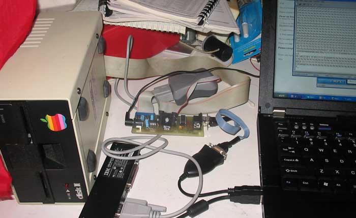
Modern PC to Disk ][ Interface
Current
board will be used to develop a hardware interface to Disk II, as
well as RWTS code that resides on micro-controller. Final
board will
need an micro controller with more memory in order to buffer an
multiple
sectors at one time. Initial debug will be through ASCII
commands sent to the AVR's RS232 port. Final version will
most likely use a USB interface for host communications. I expect
that many copy protected disks will NOT be readable through this
interface.
- Initial
proof of principal (PoP) board has been built.
- +12,
+5 and -5 volt power supplies are working
- The
voltage regulators run hot, though they are within spec. I'm
not sure if I'll do anything about this or not.
- The
drive spins when enabled
- The head can be stepped in
and out.
- So far this project is going
much smoother than that difficult PS2 to Apple II keyboard interface I
just completed. Hope things continue this smoothly.
- 12/19/2008 - I
can now read data from a floppy formatted by one of my Apple II's.
This is a significant step that only took a day to get working.
- 12/24/2008- I can now find the header of a paticular sector, and then read the data portion and verify checksum.
- I'm
limited
to a 1/4 sector buffer because I have only 128 bytes of RAM available on this
micro-controller and some of the space is needed for the stack.
Final version will use an AVR with more
memory, so that I can prefetch and buffer multiple sectors. It
will not be able to denibblize until I move to the the AVR with more
memory, but that may be sooner than expected.
- I also have written code to read every sector on a DOS 3.3 disk and verify checksum.
- One freshly formatted disk is completely scanned in 15 to 20 seconds, without error
- On
one well used disk about a half dozen checksum errors occur toward the
inside. I'm not sure if this is due to an inherant defect on the
floppy or due to my read function not performing as well as it needs to.
- Next step is to write retry and error handling code and retry a complete scan of that well used disk.
- 12/29/2008-Made lots of progress over the holiday weekend.
- Seek
and recalibrate code is in place and working pretty reliably. I
have put in place the same basic head repositioning algorythm as Apple,
with accelleration and everything else that they did. It turns
out that I'm very confused about where track 0 is located. Seems
like it is at phase 2 of the stepper motor, but everything I read and
can determine from original Apple code and schematics says it should be
at phase 0. For now I'll leave track 0 at phase 2 and figure out
what I'm missing later on.
- I still have to write the
disk spin up and spin down functions, but this should be fairly
straight forward and can wait. For now, I've implemented simple
commands to spin up the disk and spin it down manually.
- I've
improved read performance quite a bit. It turned out that reading
the sector data, converting the 8 bit disk code to 6 bits of data and
computing the checksum on the fly was taking just a little bit too
long. I would occasionally fail to get back in time to read the
first bit of the next byte off the drive. I've had to change the
read byte off the disk function to a macro, in order to save 7 cycles
on call and return overhead during the actual data read function.
This macro is only used twice in the read data loop and one other
place in a callable function for every other purpose (reading headers,
trailers, etc.). Code growth has not been too bad. I still have
about 35% of the code space available for write and format functions in
my test rig. I'll have plently more code space with the final
implementation on a AVR with much more memory and flash.
- With
this change, and the implemented seek code, I have been able to
scan quite a variety of DOS 3.3 formatted disks I have on hand.
I saw only two soft errors during this process of scanning about
a dozen disks. I suspect that the two soft errors were do to less
than ideal head positioning since they came on an outer track of a test
disk that I have had little to no trouble reading on other
occassions. The problem wasn't repeatable.
- The automatic retry mechanism is largely coded up, but disabled. At this point, I really want to know about all errors.
- So far the power supply section is holding up well, something I'll keep monitoring.
- Next
step is to code up write sector and format functions. This
promises to take a while, especially since I have a significant
homeowners project to make headway on this week.
- 1/11/2009-The write sector code is pretty close to completion.
- Must
less fun to work on than the read code. Though I haven't tested
it, it doesn't appear that the write code needs to be nearly as tight
as the read sector code.This
is largely an excersise in cycle counting. Depending on whether
the next bit is a one or zero, you change write signal or not, then
delay exactly 4 microseconds and repeat.
- There is one final
thing I need to do before actually testing out this write sector
function. That is to study the precise spacing between the end of
the sector header and the sector data in Apple's RWTS. I'll
adjust my code to match as closely as possible.
- Once the write function is completed, the last major work that needs to be done in the RWTS system is the format function.
- 1/19/2009
- I debugged the write sector code this last weekend. I can now write
sector data to pre formatted disks. Only two problems were found
in this process.
- First was a problem in the head
step function. This was what was causing the head to be on the
wrong track (see 12/29/08 note). I had the stepper motor phase
enable controls inverted. This caused three phases instead of one
to be on at once, so that the head would be positioned in the inverse
position of where I actually wanted it. For example, when I
intended to position at phase zero, I would actually turn off that
phase, and position at phase two (the average of phases 1-3 all being
on). Once this was corrected, head positioning is exactly as
expected.
- The second problem was that I forgot to index
the checksum through the write code table before writing it. This
put an illegal code on the disk where the checksum was expected.
- I've also been reviewing USB solutions. I've considered three main alternatives.
- Using
the AVRUSB driver that implements a low speed USB device completely in
software on an AVR. There are some compromises with this solution
that have probably ruled it out for me. One is the licensing
model which asks the user to publish his implementation. This
probably isn't a show stopper by itself, but there are more issues.
The implementation may not co-exist well with a firmware based
disk controller on a single processor. Both implemenations
require heavy bit twiddling by the AVR. Also the required AVR
clock rate is different than what I have designed the Disk ][
controller for. I think the solution would end up becoming
a two processor implementation in the end. And even then, it
would only support low speed USB mode.
- Next is going to a AVR
with integrated USB hardware support. This is really not a bad
hardware solution, since almost all of the deficiencies of the AVR USB
is taken care of. The main downside of this is the complexity of
integrating a solution. Another issue is the availability of
sample chips. These parts aren't stocked by regular suppliers,
though I'm guessing that ATMEL would supply samples directly to me.
This solution also requires signing a license with ATMEL in order
to use their USB PID. I still haven't completely ruled this one
out, though it may become a phase two solution.
- The most likely
first pass solution would involve grafting a FTDI chip to the front of
the existing chip. This FTDI chip implements a CDC class device
that can be simply grafted to the the UART of my existing design, with
little or no additional work. My existing test vehicle uses a UART based interface, which could
easily be expanded to support computer communications rather than a
direct human interface. I
have experience on the host side with a USB CDC device, with my shutter
tester, Also I'm quite sure that this is the fastest and easiest
solution to implement, which makes it the leading candidate for my
initial pass at the USB interface. Once the hardware and software
is implemented, I would need to write a simple host function that would
copy .DSK images to and from disks conected to modern PCs. This
certainly wouldn't be as elegant as a USB mass storage solution based
on a chip with integrated USB, but it could implemented much more
quickly. I could always implement the more elegant integrated
USB solution, as a phase two solution, later on.
- Next
steps: First I need to completely test out the write function. I
need to write an entire disk, and verify that I can read it back, both
on a real Apple II and with my controller. After that comes the
last major step in implementing the RWTS. That is to implement
the format disk function.
- 1/27/2009
- I'm in process of thoroughly testing the write sector data function
and have found that 2nd sector on a track can't be found after writing
sector 0 data.
- There is some special handling of sector
zero in Apple's RWTS format function. I'm in process of
figuring out how that affects the sector 0 to sector 1 spacing.
- 2/1/2009
- I haven't, figured out the problem with the 2nd sector, but I have
made some headway toward the format function. I've completely
reviewed Apple's RWTS format function. I started with a
disassembled copy of the RWTS code and the chapter about the Disk II,
in the book, " understanding the Apple ][".
I now have complete understanding of the format algorythm and have
created a well commented copy of Apple's RWTS format function.
This will greatly simplify implementation of my version.
- 2/9/2009
- I solved the write issue - turns out the head positioning stepper
motor apparently hadn't totally settled down in the originally alloted
time. I extended the time while holding the last phase on, and
the board now writes good sectors, every time. I have been
able to write every sector on a disk and then test it by duplicating
the disk on a real Apple. Reads are also more reliable, with this
change. I was originally using the same timing for stepper
operations as Apple. I'm not sure why it takes longer on my board
to achieve reliable stepping action, but it could be a difference in
the power supply from the Apple original. I intend to review
power supply operation during the step operations in the near future.
Other than that, it looks like putting together the format
function will be the next task I take on.
- 2/18/2009
- I am coding up the format function, but just about out of instruction
memory. I will not be able to debug the format function without
a lot of commenting out of other functions or by removing error or
debug features. Rather than spending time doing this, I
will shift focus to designing the next prototype board with USB
interface and AVR with more memory for buffers and instructions.
- 2/22/2009
- Well before giving up on the format code, I took a shot at fitting it
in the existing AVR micro-controller design. After rearranging
some tables that needed special alignment and squeezing some code into
the space between them, I freed up room for about 135 instructions.
This is after the write sector header routine, which was already
written. The Apple RWTS format code that I documented was
about that size, so I decided to give porting it a shot. Since I
had done a pretty thourough job documenting Apple's RWTS format
function, I copied the documented source directly into my AVR
assembly file. Then I replaced the 6502 instructions with
appropriate AVR code. This was easier than I could have hoped and
I still have room for about 24 more instructions! I have debugged
a fair percentage of the code with Atmel's simulator. I'll be
trying it out on an actual disk II in the very near future.
- 2/26/2009
- Started debugging the format routine with a real disk ][. I'm
able to write track 0, but verifying the sectors is bit hit or
miss, requiring too many retries so the format routine fails.
Pretty close to working, but not quite there.
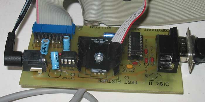
The Proof of Principal Board
Besides a small number of resistor and capacators, components on this board consist of:
| 6 pin header | AVR flash programming interface |
| 20 pin header | DISK ][ interface |
| DB-9 | RS232 communications - to be replaced by USB in final design |
| max232 IC | generates RS232 level signals - will be eliminated in USB version of this design |
| power jack | unregulated power from 12volt 1 AMP DC wall wart |
| 7812 with heatsink | provides regulated 12 volt supply from unregulated 12volt DC wall wart input |
| 7805 | provides regulated 5 volt supply from unregulated 12volt DC wall wart input |
7662 IC
| converts regulated 12 volt supply to -12 volts |
| AVR | micro-controller |
All
disk interface functions are handled directly by the AVR
micro-controller without additional logic. The majority of the board
real estate is used by the power supply and RS-232 functions.
Back to Mike's
Hobby Home Page