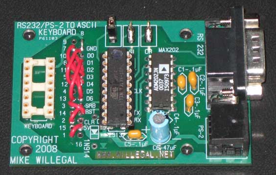
Built Up Kit - Configured for the Apple II
ASCII to PS/2 Keyboard Adapter
This board converts either a PS/2 keyboard
input or RS232 input into a ASCII keyboard interface. It
has been tested with the Apple 1 and Apple II models, but other
vintage computers that take a parallel ASCII keyboard interface
should work. Apple IIe and later Apple computers will not
work with this interface. See my blog
or video podcast for more
information.
Version 3.0 Firmware Changes
In order to allow support of different styles
of ASCII parallel keyboard interfaces, options for additional
styles of strobe handling has been added. In
addition to disabling control-RST and control-CLR functionality,
inserting the CR jumper also causes the SRB output pulse to be
maintained until CLR, which becomes an input, is asserted
(high). When the CR jumper is inserted, connecting SRB output
directly to CLR input, will result in the normal 125
micro-second pulse. If you connect the SRB output directly to
CLR input with an appropriate resistor (say 10K) and connect the
CLR input to ground with an appropriate value capacitor (say
.1uF), you create a RC timing circuit which can be used to
extend SRB. The aforementioned values will extend strobe to 1
millisecond, but other values can be used to set the timing to a
value that you desire. With the CR jumper inserted, the CLR TTL
input can also be connected to external logic which can
terminate SRB in any arbitrary fashion.
Features:
- Use a regular PS/2 keyboard on Apple II or other vintage computer that accepts ASCII keyboard input
- Upper and lower case support
- Support PS/2 numeric keypad (numeric mode only - cursor controls will not work)
- Use PC terminal program (hyperterm) running on modern PC, for vintage computer input device
- Echos PS/2 keyboard input to RS232 TX for input logging purposes
- cntrl-R - cntrl-S - cntrl-T reset sequence pre-programmed
- You can use terminal programs on a PC to send scripts of commands to target computer keyboard input interface. This is an easy way to load programs into vintage computers that otherwise must rely upon unreliable media, such as a cassette interface.
- Can be adapted to other vintage micro-computers by rewiring connection to target PC
- Operates from +5 volt supply (amperage requirements to be determined shortly)
- RS232 runs at 9600 baud
- Shift lock support - sending commands to change the LED status on the keyboard is trickier than one might imagine, but I finally have it working
- Arrow mapping to Apple esc-char cursor movement (Apple II specific)
- Cntl-Alt-Del reset support
- Easily jumperable keyboard 16 pin socket pinout - will allow apple 1 and other vintage computers with DIP16 header connections to use straight through ribbon cable connection
- Clear screen strobe support using cntrl-C cntrl-L contrl-R sequence (intended for apple 1)
- Optional automatic reset and clear screen after power up
(version 2.2 and forward)
- Support for stretching strobe and holding strobe until acknowlegement (version 3.0 and forward)
Download Source and HW Files
I no longer sell kits or boards, but you can download the
assembler source and hardware CAD files and build your own PS/2
adapter.Note that;
high fuse byte should be programmed to: DB
low fuse byte should be programmed to:E2
Before you download, understand that you will be on your own and assume all risks associated with this project.
Software Files: SWfiles.zip
Hardware Files: HWfiles.zip
The RS232 port requires that the AVR RC-oscillator be calibrated - here is the procedure.
Calibrating and programing is a four stage process. The calib and operation FW are built from the same source. Look in the source for a .IFDEF CALIB to see the difference.
When booting the calib image, it will output a square wave out port B.
The calibration is done by connecting a terminal to the serial port and typing one of the following 4 commands.
I – this increases the calibration frequency
D – this decreases the calibration frequency
W – this neither increases or decreases frequency
Q
– this quits the calibration process, displays the calibration
variable, writes it to the last location of EEPROM and exits the
calibration process
You need to connect a frequency counter or scope to one of the “B” port outputs and either increase or decrease the frequency until it is as close as possible to 1Khz. These days, many inexpensive meters have frequency counters that will be accurate enough for this job.
The AVR will not echo the correct character to the RS232 port, when it is out of calibration. The calibration routine will default to decrementing the calibration value if it receives a character that it doesn’t understand. Just keep typing and eventually it will wrap around into a good range, at which point you can fine tune it.
So the four steps are:
1)
First load the calib file (AVRPS2_keyboard_calib.hex) and run it to
adjust the frequency, as described above. When you have the frequency in
a good spot, type Q and the the controller will output the calibration
value and also writes it to the last location of the EEprom. For record
keeping purposes, it is a good idea to write the calibration value with a
marker on the underside of the chip when you are done.
2) I have an AVR dude script that reads the EEPROM – I would run this to get the calibration value into a hex file.
3)
Now you can program the regular firmware (PS-2keyboardv3.0.hex).
Unfortunately, with AVRdude, this process also erases EEPROM, so you
need to reprogram the calibration value into the last byte of the
EEPROM.
4) Reprogram the calibration value into EEPROM using the
AVRdude script provided, using the EEPROM file you read from the system
in step 2 and you are done.
If you are doing a batch of them, once you get things set up, it takes only about 30 seconds or so to go through the scripts, to calibrate and program, each part.
In this design, it would have been nice to use a crystal for clock generation to avoid the calibration hassle. However, that would take two pins of the AVR, which I didn’t have available. I could have freed up a couple of pins by configuring the settings with the keyboard or serial port. It would have taken time to write the software that I didn’t have available, as, at that point, I was in the middle of the inital Apple 1 cloning effort for Mimeo.
This Project was Inspired by Other Peoples Work
- http://seb.riot.org/appleII/keyboard.sml
- http://www.scienceprog.com/wp-content/uploads/2006/08/AVR313.pdf
- http://www.brielcomputers.com/wik/index.php?title=SuperE
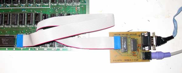
First Prototype Adapter Hooked Up to an Apple II on One End - a PS/2 Keyboard and a PC via RS232 on the Other
Questions: send mike@willegal.net an email
Back to Mike's Hobby Home Page