A general update.
By now, I have already acquired or have sources for almost all of the components, though I am still working out the exact source for some supposedly common parts like capacitors. Even the easy stuff hasn’t been easy on this project. For example, the A1 used a lead spacing of 300 mills for decoupling caps, which is not common today.
Unfortunately costs have risen to the point where my cost per unit has exceeded the current selling price for an A2 motherboard replica kit. I don’t know how Steve Gabney sold his kits at the price he did. I suspect he isn’t responding to emails because his costs equaled or exceeded his selling price making his efforts a losing proposition in business terms. I hope that my final selling price doesn’t scare off too many hobbyists. At this point, I’m toying with either a 555.55 or 666.66 number. I may use the second number for assembled units and the first for kits.
Once I set the price on these units I will not budge. Lowering the price on the A2 rev 0 replica, like I did, really hasn’t greatly affected sales. Regarding the cost of the A2 rev 0 replica, I am planing on raising prices, a bit, once this batch of kits is sold. I still am in the red on that project. It’s not worth repeating the effort of gathering components for these complex kits unless there is some kind of return on investment. The only good thing concerning costs, is the recent sale of an original A1 for $50,000. That should put things in better perspective for buyers. Also I’ve only seen a single original A2 rev 0 on eBay all year. I would expect that some demand is building after a couple A2 rev 0’s went for what I consider bargain prices in 2008.
As far as the PCB layout goes, I have the first pass completely done. I’m in the first fine tuning pass. I’ve had one of the online PCB vendors run their free DFM check on it and it’s found a few issues, which I need to deal with. To give you an idea of the difficultly and the attention to detail I’m putting into this project, the CAD file on this project is currently 50% larger than the final A2 rev0 CAD file, even though there are only 2/3 the number of components. In real numbers the CAD file is 500K bytes long versus 336K on the A2 rev 0.
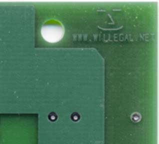
For those that wonder how they will be able to tell my replica from an original, I put a small logo in the copper layer on the back corner of the board. Here is what it looks like on a rev 0.

Finnally I started a webpage to be used as a source of information on the A1 replica. It is at http://www.willegal.net/appleii/apple1.htm

