Monitor Commands Are Working!!!

Well I did plug the keyboard in backward and fried a 74LS00 chip on the keyboard. Fortunately I have spares in my stash. Once fixed and plugged in correctly, I get a monitor prompt after reset and can enter small programs. I only now realized that the monitor isn’t really the same as the Apple II monitor and I’ll need to round up or create a manual, since the Apple 1 operations manual only lists the source code.

The kitchen counter is the lab this week.

Next step is to solder in the edge connector and see if I can get a borrowed cassette interface to function.

One last editorial comment. For a long time, while working on this project, I really just didn’t feel very attracted to the Apple 1. It just seemed too primitive and lacking in features, especially compared to it’s offspring, the much more sophisticated Apple2. However, I now have to admit that I’m starting too develop a fondness for this straightforward machine. For one thing, troubleshooting problems seems to take half the time or less compared to the Apple 2.

power up

A ton of progress today.

I cleaned the soldering junk off the board this morning and let it dry until I came home from work.

I hooked up the PEM (power entry module) with no chips stuffed to see if the power supplies were ok. Powered up and checked the voltages and they all looked reasonable.

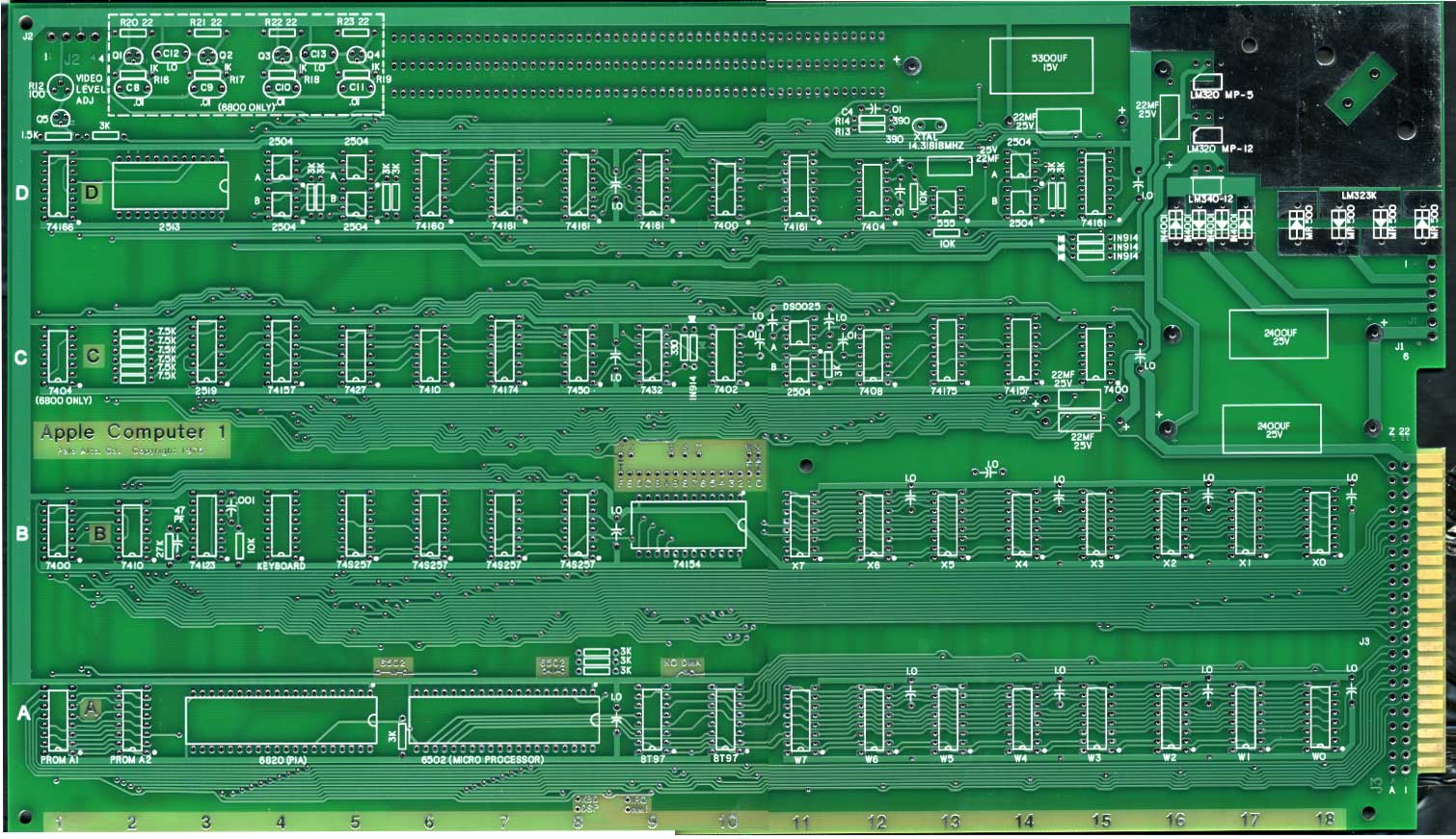
Next I stuffed the stuff necessary for a video display. That is rows C and D plus B2 (I think that was the row B chip).

Modified a video cable to connect to the connector on the board and got my monitor out. I plugged everything in and sure enough I got a display. Felt around the board for hot chips and nothing seemed very warm. Powered off and powered on again and nothing happened. Checked voltages and nothing. Somehow the 500 milliamp fuse in the PEM was blown. Replaced the fuse and tried again and the display came back as before. It had a bunch of pretty much random stuff, including a lot of @ signs. It was a little strange in that during initial power up, the contents of the screen would scroll up till near the top of the screen and then stop. I’m not sure if that is normal or not for an Apple 1.

Here is a picture of the set up.

I jumpered clear screen to +5v and sure enough the screen cleared out. Things seem pretty promising.

I now stuffed the remaining chips, which actually wasn’t much and one bank of DRAM. I then soldered the 6502 jumpers and the address selects for PROM (0xf), 6820(oxd) and the bank of DRAM to address 0. Powering up again, I got the same screen contents. Shorting reset to ground got nothing. Ok now it’s getting late, do I call it a day or not.

Well I decide to get out the oscilloscope. I spent a bit of time figuring out that one of my probes is dead. After switching probes, it quickly becomes evident that there is no processor clock because I didn’t connect the NO DMA jumper. That jumper is only left open if there is an expansion card attached that drives that signal. Ok a blob of solder connects that jumper. Now I get what appears to be a prompt, after reset, but also some other characters. Time to get out the keyboard.

The keyboard is attached but when I hit reset the power light on the keyboard goes out and the computer doesn’t respond to keystrokes. I decide it’s late, time to update the blog and get some sleep. After shutting down I think I realize that the keyboard cable is connected backward. Oh well, it is late – I’ll pick it up tomorrow.

Apple 1 Clone Build

Fully soldered and ready to see it’s first electrons. I did leave the expansion connector off for now, it’s not essential for operation and leaving it off offers the ability to scope the bus at it’s location.

The only surprise so far, is that the large heat sink extends a tiny bit beyond the edge of the board. Reviewing pictures of the original shows the same thing, so all is well. I was a bit worried about how the large 5 volt regulator and heat sink would go in, but no issues at all. I put a little thermal grease between the regulator and the heat sink and bolted it in with some 6-32 by 3/8″ screws I found at Home Depot.

I’m not real happy with my decoupling cap selection, since they are much smaller than the original. I’ll probably replace them at some point.

First test will be of the power supply without ICs installed. That will take place tomorrow.

Assembly progressing

Here is an image with the sockets in place. Note the 24 pin socket for the 74154 in the center of board is in backwards – I should follow my own instructions. 🙂

A1 being assembled - sockets in place

First Boards Arrive

They are looking good, so far, can’t find any obvious faults. Will have to build one up and see what happens.

Here are a couple of images, one of the front, the other of the back, of the bare board.

By the way, these scanned iamges don’t really do the boards, justice.

Apple 1 PCBs due to arrive on Monday.

Look me up on AIM on Monday – “illegalwithaw” at 9:00 PM EST and join the group chat. I hope to be able to post images of the boards and let you know how they are looking.

I just received the decoupling caps, the last components I had on order. Though they will be functional, I’m not happy with them, since they are so small, unlike anything used on an original. I’ll try ordering a different decoupling cap that will hopefully look a lot more like the original, and the ones I don’t use on the prototype will go into the scrap box.

I’ve figured out the solution to the keyboard-PS/2 reconfiguration issue. I’ll put in a double row of KK type header pins. They make housings that can be individually wired and plugged in. This way, you’ll be able to make up several headers that suit your needs and just plug in the one you need. Unfortunately, it’s going to add some cost to the device, but I think it will be worth it. Here is a link to a housing as seen at digikey.
http://search.digikey.com/scripts/DkSearch/dksus.dll?vendor=0&keywords=649-69176-028LF
Software changes aren’t necessary for this, but I’m going to reassign outputs on the AVR, anyway, in order to clean up the PCB. I’m going to try to find time to build a prototype unit this weekend.

PS/2 to ASCII keyboard interface update

I spent some time last night coding up the last software features I wanted to implement for this device.

I still have to do the following before I can offer you some kits or built and tested boards.

1. test new software changes in AVR simulator
2. build a new prototype with hardware changes
3. test new software changes on new prototype with both Apple II and Apple 1
4. getting a quote on a run of production boards and cost of parts
5. figure out pricing and quantity I”ll build
6. purchasing parts and PCBs
7. writing a short instruction manual

Toughest task is building the proto board, and I have some time before the A1 PCB’s arrive in which to do that.

The original plan was to pin out the 16 pin socket for a default compatibility with the Apple II. Apple 1 users would have to cut some traces and add jumpers for the Apple 1 pin out. I am designing the board so that this will be easy to do.

As I was sitting here typing, I realized I may be able to do a soft configuration change between apple 1 and apple 2, so that no hardware cuts and jumpers would be necessary.

I guess the SW isn’t really done, after all. I’m going to have to look at what it would take to reconfigure the AVR so that cuts and jumpers become unnecessary when moving between A1 and A2. In any case, I’ll leave the option to do hardware cuts and jumpers in the HW design, in case users of other vintage gear need to configure the pinout differently.

Apple 1 update #17

This weekend I completed two small projects I needed in order to bring up the Apple 1.

First was what I am calling a power entry module (PEM). This contains the transformers, on/off switch and fuse. As this point I’m not planning on including the switch and fuse and associated wiring with the kits, since choice of components depends alot on the type of enclosure you will be housing your Apple 1 in. For initial bringup, I’ve put together the PEM, so that I don’t have exposed 110 volt wiring near the computer while I’m working on it. Eventually I plan on building a nice acrylic case for everything, but that will come later.

Note that in building this unit, I was reviewing the instructions in the Apple 1 operations manual. The diagram had the switch on one side of the AC line and the fuse on the other. Keep in mind that I’m far from an expert in this area. However, I’m thinking that this isn’t a very safe design. Common household wiring normally has 3 wires, commonly called the hot, common and ground. The hot sources the voltage and common is the return. Normally the common will be close to a ground potential. If the switch is connected to the hot wire and the fuse the common, then if the fuse blows, and the switch is left on, then there will be potential voltage in the system, just with nowhere to flow. If the reverse is done, then there will be potential voltage in the system anytime the system is plugged in, unless the fuse blows. I’m thinking that the proper way to wire this system is to put both the fuse and the switch on the “hot” wire” and then if either the fuse is blown or the switch is off, then there will not be potential voltage in the system. Please let me know if you think that I am off base here.

Second thing I put together is an Apple II to Apple 1 keyboard converter. This was done using a couple of spare wirewrap sockets and some perf-board, all out of the scrap box. The total cost was nil. John Calende has a nice blog describing what needs to be done.

http://apple1computer.blogspot.com/

Here is my quick and dirty wirewrapped version, mounted in a small wooden box I made from scrap wood. I’m thinking of adding a clear screen button to this converter.

Apple 1 update #16

Cameron Cooper, who has been a great asset in finding parts, is putting together a new web site called apple-1.org. We are planning some scheduled chat sessions that will be hosted from his site. The first one will be held the evening after I receive the A1 boards. Topic’s are open to Apple 1 related stuff, but I hope to post a URL to images of the PCBs boards- so this will be the first public viewing, so to speak. I’ll post the time and date for this chat session as soon as UPS gives me the date that the PCB’s will arrive. Meanwhile hop on over to Cameron’s site and get registered.

According to the status on the Advance Circuits web page, the boards are built and in the shipping department, due to ship Monday. I’m far more excited about these boards than I think I was with the rev0 boards. Could be a couple of factors at play here. First of all, this board seems to me to have been far more difficult to reverse engineer that the A2 rev 0 was. I though I would have an easier time on the A1 because of the experience of the A2rev 0, but the A1 effort turned out to be even larger. I believe that the A1 was original designed with the idea that a silk screen and possibly solder mask were expensive options, so a lot of legend information was added to the top copper layer. Also the power supply section was pretty tricky. There is more interest in this project than there was on A2 rev 0, so I think that that is adding to the excitement, as well.

While I’m waiting for the PCB and last parts to be delivered, I’ll be working on two things.

1) The A1 assembly manual.
2) The PS/2 to keyboard adaptor. I’ve decided to make a batch of these. They will default to an A2 configuration, but will easily be altered to a A1 configuration, and I’ll provide instructions. Here is what the top artwork currently looks like.

Cameron and I are also investigating a possible vendor of new parallel ASCII keyboards. This same vendor was advertising in the Hobbyist magazines the 70’s and still lists ASCII keyboards with parallel interfaces in their catalog. In fact the current keyboard appears to have the same key layout as can be seen in those 1970’s era adds. Hopefully they still stock them and the price is reasonable. Original ASCII keyboards are very, very difficult to find. The only reliable source I know of, is from the Apple II+ systems that are frequently sold on ebay.

Finally, if you are interested in a A2 rev 0. kit, remember that the price is going up on Feburary 1st.

Apple 1 update #15

Well, I’ve ordered the last components I need, and also ordered a batch of PCBs!

For the past few weeks, I’ve been fine tuning the PCB, slowly improving fidelity to the original. Every few days I would find another little feature in the original, that I didn’t notice before. Almost all of these changes are cosmetic and wouldn’t affect functionality. Last cosmetic improvement was this morning. I guess I finally decided that it was close enough. To be truthful, I’ve been worried about accidentally breaking something functional. Getting boards of this size made, is very expensive and a batch of bad boards would set me back a pretty penny. I should have the PCBs within a couple of weeks. Next step will be assembling, testing and writing the assembly manual!

My waiting/interest list for kits is small, but steadily growing. If you are interested, send me a line and I’ll add you to it. If you are not an experienced electronics kit builder, or not completely comfortable with hooking up transformers to 110AC. I would recommend starting with one of Vince Briel’s A1 kits, which are significantly easier to put together for a variety of reasons. Once I get the first set of kits together, I’ll be offering them for sale, first on the list, first opportunity to buy. This should be sometime in Feburary.

In case you have been following my non-Apple 1 blog entries, the loose fuel line problem on my Malibu has been rectified and the fuel gage is operating perfectly.