Quite a few posts ago, I mentioned that I was using bench power supplies to run my SCELBI and that I would update the blog with more information, as I progressed in getting a more suitable, power supply solution. Well, this is the the next post, in what promises to be a series.
What I have done is get a couple of Power-One linear supplies to power the SCELBI. Obviously one needs to be 5 volts and the other at -9 volts. The reason why I selected the Power-One’s is that I know that Nat Wadsworth’s 8B development system used a couple of Power-One supplies.
We know that at the time, a couple of the more experienced SCELBI builders made their own supplies. For instance Circuit Cellar’s Steve Ciarcia made his own for his SCELBI. I’m not that experienced with power supplies or that adventurous. We also know from the price list, that SCELBI Computer Consulting sold supplies. I only know of 1 or 2 of those in existence, and I don’t have details on what is inside the aluminum case, but I’m guessing that there are two Power-One supplies, one for each voltage.
So the only details that we have from back in the time is Nat’s system, and a couple with home brew supplies. We know that Nat used the following Power-One supplies in his system.
C5-6: rated for 5 volt, 6 amps
B15-1.5: rated for 15 volts at 1.5 amps
The C5-6 can supply plenty of power for any SCELBI. The B15-1.5 is a 15 volt, 1.5 amp supply. Nat obviously modified the B15-1.5 to supply the -9 volts for his SCELBI 8B.
I did some research and found that Power-One still makes nearly the same supplies. They have been updated a bit to support international mains power, but they are very similar to the ones that Power-One built back in the 70s. Here is a link to the current product specs from Power-One’s website.
http://www.power-one.com/sites/power-one.com/files/documents/power/datasheet/lin.pdf
The C5-6 is now called the HC5-6/OVP-AG. The B15-1.5 is now called the HB15-1.5-AG. Thinking I wanted to recreate Nat’s power supply setup, I did some search and found that these supplies are widely available, but fairly expensive. I also found that numbers of them can be found on ebay, sometimes in older variations and similar models are available from competing vendors, with almost the same model names.
Trying to save some money, I found two NOS units of fairly recent vintage on ebay and purchased them. Both arrived as advertised, in excellent shape in original packaging. I chose to get newer units, since I didn’t want an older unit blowing up my SCELBI

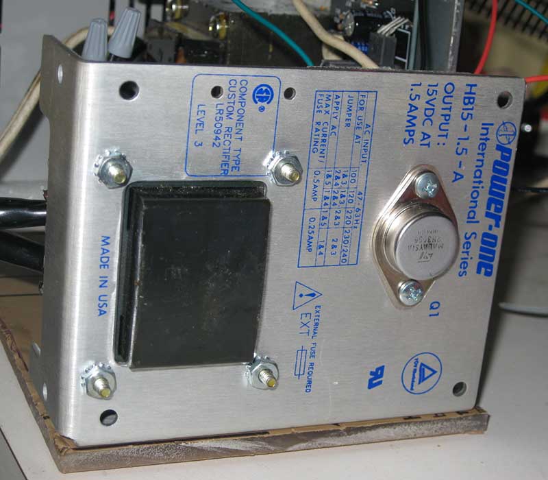
Power-One 15 volt supply
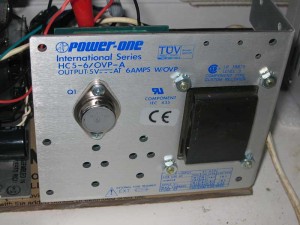
Power-One 5 volt supply
Now my next challenge was to modify the 15 volt unit to supply 9 volts. I’m not going to tell you exactly how I did this, because I don’t want to be sued in case you blow up your SCELBI or yourself or your house. If you don’t know what you are doing, get some help before you do some damage to yourself or your possesions.
I will tell you that I spent the better part of a morning reverse engineering the circuit, making the modifications and testing them. There is a very nice site on hacking on these power supplies, that you should check out, if you are new to this.
http://www.djerickson.com/p1hack/
As part of this process, I calculated the power consumption of the power transistor. The original 15 volt supply had the input to the power transistor at about 26 volts. With a drop to 15 volts at 1.5 amps. This means the power transistor was consuming about (26-15)*1.5 = 16.5 watts. The 2N3055 power transistor is rated to up to 115 watts, though this is under ideal conditions. I figured that running the power supply at 9 volts would increase power consumption to (26-9)*1.5 = 25.5 watts. I figured the power transistor could handle this ok, so I went ahead and made my changes. According to the information I’ve read, the most common failure mode of these power transistors results in essentially a short of the input to the output. This sort of failure will kill almost every IC on your SCELBI, unless the on board fuses blow first, so make sure that you put proper rated fuses on each of the PCBs, as you build your system.
The changes I ended up making involved removing a resistor and adjusting the voltage. I did some basic testing and tweaking and decided I was ready for the next step.
The next step was configuring the two supplies so the B15 supplied -9 and the C5 supplied +5. This was pretty simply done by connecting the B15 supply’s plus output to the C5’s minus output. I put them on the same power switch and powered up. Voltages and everything else looked fine, so I went onto the next step.
At this point, I took one last power check with my existing bench supplies after adding a second SRAM card, which I have just completed building. The 5 volt supply went from 2.2 amps to 2.4 AMPs, meaning each memory card was consuming about .2 AMPs on the 5 volt side. The C5-6 AMP supply was going to be overkill for a full 4K SCELBI, but Power-One’s next smallest supply was only 3 AMPs and this would have been marginal for a full 4K system.
Next, I looked at the bench supply that was suppling -9 volts. It’s meter moved from about .5 amps to .7 amps. This was only an increase of .2 amps, which seemed a little small to me, but since the system was running fine, I didn’t think much about it at the time.
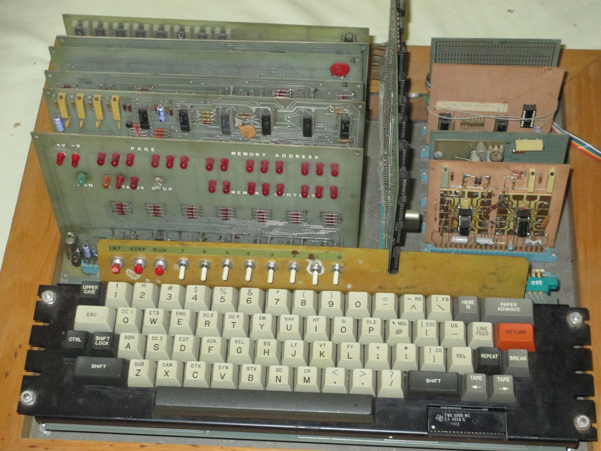
Now I was ready to go, and connected the new supply to my SCELBI. Here is what the setup looked like for my trial. Note that this was for trial purposes only, and as soon as I can, I’ll be doing proper wiring, enclosing it, adding a fuse IEC connector and a switch.
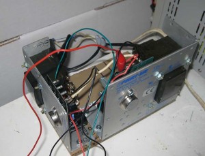
Power-One supplies
Note that I have kept the transformers as far apart as I could and put them at right angles to minimize interference between them. Also note that the cases of the power transistors carry live voltages, and are not grounded. I’ll have to protect them from accidental shorts or figure a different way to mount these supplies.
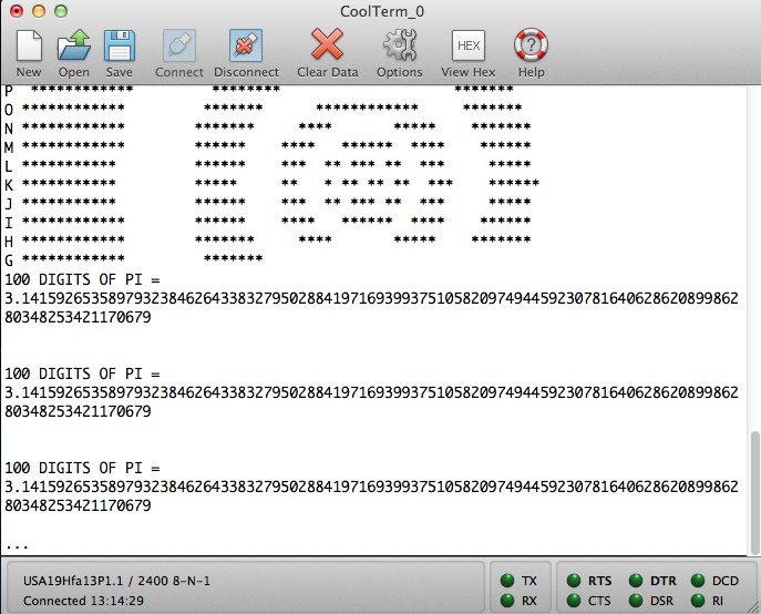
I powered up and ran some simple tests on the SCELBI and everything ran perfectly. So what is the miscalculation that I mentioned in the title of this post. Well I did notice that the power transistor on the B15 supply was, pretty warm. Warmer than I would have expected for supplying only .7 AMPs.
Since I had both a new supply and a new memory board, I decided to figure out just how much power this supply was providing. On this supply there is a .22 ohm power resistor that is used for sensing current for the current limiter circuit. By measuring voltage drop over that resistor, with a meter, I could calculate current. Using my old, non precision, Sears meter, I got about a .3 volt drop. Using ohms law, I=V/R, I calculated .3/.22 = 1.5 AMPs. This is substantially more than the bench supply’s meter showed.
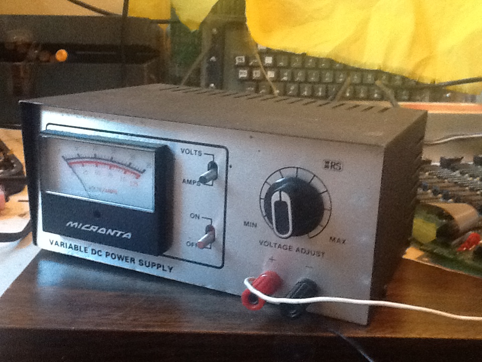
Because of this, I decided to unhook the B15 and do some tests with both my bench supplies. First was the old Radio Shack supply that I was originally using for -9 volts.

Micronta 22-123
It still showed .7 AMPs, however when I measured the voltage, it was only putting out around 6 volts. Clearly the supply was current limited. The interesting thing its that the SCELBI seems to run Ok at this voltage, though I wouldn’t recommend doing it on purpose.
Since this supply is supposed to supply 1 AMP, either the meter was off or the current limiting was kicking in too soon. Putting the new 6 AMP bench supply in place of the old Radio Shack supply showed current consumption of about 1.3 AMPs, close to what I had calculated across the B15 power resistor and way too much for the Radio Shack bench supply. I removed 1 of the SRAM cards and it dropped to .7 AMPs. So each memory card needed about .6 AMPs of -9 volts, way more than the .2 AMPs that the Radio Shack supply showed.
My miscalculation is that Nat’s 8B system with it’s 2102 SRAM and PROM board apparently draws much less power than a 8H with it’s 1101 SRAMs. I should have paid attention to my old power supply post and gotten a beefier Power-One supply to support -9 volts. I guess that sometimes we get so tied up in recreating something, that we don’t pay attention to differences between what we are doing and what someone was doing in the days gone by.
For now, with 2K of memory, the B15-1.5 should be fine, though it runs a bit warm, and I wouldn’t dare run it in an enclosure without fans. In order to grow my system to a full 4K, I think a supply that supports 3 AMPs will be fine. Looking at the Power-One literature, I’m thinking that an HC12-3.4-AG might be the best choice. Stay tuned for more on the SCELBI power suppy saga.