Improved Apple Teletype Emulation

A previous post showed how I attempted to connect the SCELBI TTY to an Apple IIe with an old serial card that supported current loop. Well I’ve been working on some of the issues and now have it working good enough to post some of the details. With the standard Apple 80 column scroll routine, I can only reliably get 8 lines to scroll at 110 baud, but it’s working pretty decently, with that limitation.

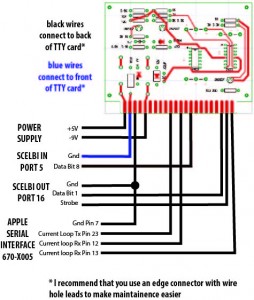
First of all, here is how the TTY card is connected. The standard SCELBI MEA software assumes these port assignments.

Apple Serial To SCELBI TTY Connection Diagram

Apple Serial To SCELBI TTY Connection Diagram

If you try repeating this experiment, be aware that there are two versions of the Apple Serial Card firmware,. However, since I don’t use the standard driver, it doesn’t matter which version you have.

The simple TTY emulation source code can be downloaded from www.willegal.net/appleii/ttyemul.asm. It is written to use an assembler called DASM, which can be found and downloaded with a web search.

You can experiment with changing the window size by changing the second line in the program. Note that I started with a “hijacked” version of the original serial card driver, but it has been greatly modified. This code assumes a IIe with 80 column card. For display, I had a lot of issues getting CR not to send a LF, but still return to beginning of the line. I also implemented a bare bones bell that sounds only if no characters are coming in.

I suppose a custom “fast” scroll routine might help with increasing the window size, but I haven’t had time to work on that. I think I left enough of the original Apple II peripheral card software mechanism in place, that it wouldn’t be too hard to move the code to PROMs that would reside on the serial card itself. For now, it assumes slot 2 for the serial card, and slot 3 for the 80 column card. Let me know if you have any luck with this.

I’m using a modified version of this software as the basis for my Apple II RTTY software, but the transmit side of that implementation needs some work. I want to create a way to type in some canned strings for transmitting CQ with a call sign and so forth.

Macintosh 400K Floppy Rescue

I’ve been on a lookout for a 400K external floppy since restoring the 128K Macintosh that I obtained a while back. Operating a 128K Macintosh without an external floppy is extremely painful. I did have an 800K external floppy, back in the day, but I sold it some time back.

Back in November, I picked up a couple of broken drives off of ebay for $70, shipped. I thought that this was a pretty good deal, as good drives often go for over $100.
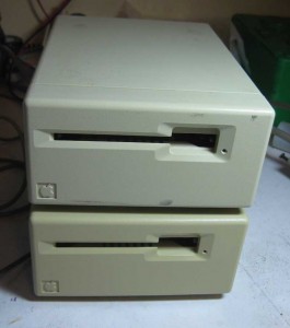
Mac 400K Floppy Drives

Mac 400K Floppy Drives

From my experience resurrecting the internal 400K drive, I knew that these units were very well built. I was thinking that I could probably get one of the two working. Maybe if I was lucky I could get both going and sell one to pay for my purchase.

When I received the units, I opened the box, only to discover that the units had been taken apart, and weren’t even completely reassembled. This concerned me a great deal, as I expected that when I found time to dig into them, that I would find that some inexperienced hacker turned a broken unit, into a broken beyond repair unit. I didn’t have time, to do any further analysis and the units were stacked at the rear of my workbench until time allowed me to dig into them.

Well, yesterday, I found that time. First thing I noticed is that all the screws holding the chassis and enclosure in place were gone, except for one. I pulled the first mechanism out of the chassis and took a look. The auto-eject mechanism was completely bound up.
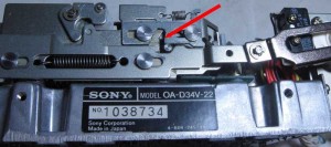
Mechanism Hang Up Point

Mechanism Hang Up Point

Some of the components were bent, apparently from someone trying to force the mechanism open. One lever was actually completely frozen on it’s pivot. I disassembled the components that could be removed and cleaned off as much gunk as possible. It took a bit to free up the frozen lever, but it soon was operating smoothly. I straightened the bent components and checked the mechanism out. I noticed that sometimes a roller bearing would hang up partly through it’s movement, locking up the mechanism. I took a small file and filed a bit off of where it was hanging up, and the mech started working almost like new. With that problem, this unit might might have been misbehaving from the day it was made.

Now I reassembled the drive and attached it to my 128K Macintosh. The computer recognized the drive and it appeared to operate normally. I was able to format floppies and exchange them with the internal drive, so alignment and operation was perfectly fine.

I thought, maybe I’d be that lucky with the second drive and I put the first drive aside. Before doing anything else, I figured I would clean the mechanism of the second drive. It seemed to have much less wear then the first drive. I closely examined it and the mechanical pieces seem to be in excellent shape. After cleaning, lubing and reassembling, I hooked it up.

After turning it on, the stepper motor moved the head to the inside track and continued turning. This one had some kind of problem with the control system. I tried a lot of things, including swapping controller boards with the other drive with same result as before. I decided that it was pretty likely that the sensor that indexes the heads to the outer track probably was not working.
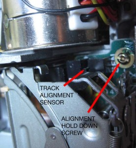
Track Alignment Sensor

Track Alignment Sensor

After some more mucking around, I decided to do a search on the internet and came up with a “Click of Death” result that matched my problem. It seems that I was on the right track, and it was very likely that the head indexing sensor wasn’t working. I removed the mechanism again and used a sewing needle to try to clean the tiny slots in the sensor. The needle seemed to draw away some kind of oily residue from the slot. I kept at it until I didn’t see any more of the oily residue. I wonder if someone had sprayed something into the drive as part of a vain repair attempt.

I put the drive back together and I was in luck, as the “Click of Death” was gone and the drive seemed to boot normally. However I encountered a new problem. This drive’s alignment didn’t match my other drives or the old disks that I still had from back in the “old days”. This was clear, as floppies formatted and created on this drive would only boot and be read on this drive. Floppies created on other drives would not work in this drive.

This created a bit of a dilemma for me, as the factory seal on the alignment mechanism still was present. Either the factory alignment was off or somehow the problem with the sensor had affected alignment. I tried cleaning the sensor again to see if it would get better, but had no better luck. After much thought, I decided that I had no choice, but to muck with the factory alignment to try to make it better.

Normally you will align a floppy drive with special test software and a calibration disk and some test equipment. I have neither the software or a calibration disk, so I figured that I would just try to “wing it” by getting it to read disks made on my other drives. The alignment setup can be accessed with the unit completely assembled.
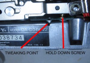
Floppy Alignment Points

Floppy Alignment Points

You loosen the hold down screw just a bit, so that the board holding the optical sensor can be moved back and forth, but not so much that it is completely free. On the side of the chassis is a groove that matches a groove in the board. Using those grooves, you can use a flat bladed tool to tweak the board in very small increments.
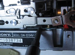
Tweaking Alignment

Tweaking Alignment

After a lot of tweaking and testing and re-tweaking and re-testing, I have the second drive working as well as the first one. I wonder if this drive had problems with alignment from the factory, which is why the mechanism seems to have had so little use. I also continue to wonder if the problem with the index sensor had affected alignment. In any case, the drive functions well now, and floppies can be freely interchanged with my other drives.

Once I pick up some M3-.50 by 8 MM screws with matching star washers, I’ll be able to put both drives back together. I’ll probably sell the extra drive, as I just don’t see the need to keep a back-up parts drive.

Kenwood TS-530S Alignment

Vintage radios work exclusively in the analog domain, with alignment done by adjusting numberous discrete coils, capacitors and resistive elements in the system. This is vastly different from my experience with digital computers, where, for the most part, the equipment works or it doesn’t and seldom is tuning required.

Though my Kenwood transciever has been working pretty decently, it did have one apparent issue that made me think that it needed an alignment. When switching from USB (upper side band) to LSB (lower side band), the “tone” of the audio output changed a little bit. I didn’t think that this was correct behavior and have been intending to do an “alignment”, which involves following a rather involved 25 step tune up proceedure. This is one reason that I have been acquiring test equipment, like the Marconi signal generator and Fluke counter.

Yesterday, I spent a couple of hours in which I started the alignment process. I made it through steps 1 through 7 of the 25 step process. Oh, and I also had to skip ahead and do steps 11 and 17 when I adjusted components on the IF board instead of the PLL section ruining previous settings. As I move through the rest of the steps, I’ll have to redo those steps as the intention of the process is to do things in a certain order. This is so that later steps don’t ruin the settings of earlier steps.

I found that the job takes a lot of time, but I didn’t have any particular difficulty with any one step, other than adjusting the wrong components. This makes me think that the sections of the radio that I have adjusted don’t have any major problems.

The good news is with the completion of these steps, the difference in audio from the LSB and USB has disappeared and no other ugly phenomena has surfaced. I must be doing something right, or else I’m pretty lucky.

The reason I stopped at step 7, is that steps 8, 9 and 10 requires either going through a range of frequencies manually with a signal generator or the use of a sweep generator. I started working on building a sweep generator a month or two ago, so I’ll wait until either the sweep generator is working or is given up as a failure before continuing with the alignment. I’ll talk more about my sweep generator project in a future post.

Posted in HAM

Video Posted Showing RTTY RX with Vintage Gear

Check out my latest podcast.

feed://www.willegal.net/feed.xml

The Radio Teletype receive function seems to be working real well. The work I did in the “lab” preparing for this, resulted in almost immediate success upon hooking up my rig to a real HAM receiver.

Before I can start transmitting over the airwaves, I still have to do some work with antenna tuning, write an Apple IIe RTTY transmit driver and generally check things out in the lab. I also have some kludged cabling going on that needs to be fixed.

That said, I think that KC1CKV will soon be on the air…

73

HAL ST-6 RTTY TU Restored to Operating Order

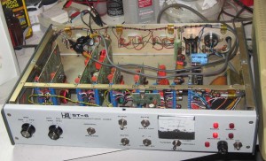
In a previous post, I showed a picture of my HAL ST-6 RTTY Terminal Unit.

Now that I had the SCELBI 8B working, in my spare time, I have devoted a few hours to getting the ST-6 up and operating. For those of you who aren’t aware, an ST-6, demodulates a Radio Teletype (RTTY) signal and presents a current loop data stream to an external device. It was intended for connection to a Teletype, but I’m connecting it to my vintage computers.

The HAL ST-6 is quite a different beast, as compared to the computers I’ve been working with over the years. There is a lot of hand wiring in it, and each module is filled with discrete components along with a few op-amps.

inside the HAL ST-6

inside the HAL ST-6

The RTTY signal comes in several forms. My mid 70’s era HAL ST-6 was designed to support demodulating a signal with frequency shift keying offset of 170, 425 or 850 Hertz. Instead of a teletype, my plans are to have a vintage computer decode the serial stream and display the incoming data. I’m starting with an Apple IIe and have written a driver for the old serial printer board that supports current loop. The driver reads 45.45 baud 5 bit BAUDET format, converts it to ASCII, and displays it on the screen. Eventually I hope to be able to port this code over to a SCELBI.

For testing purposes, I’m using an internet RTTY audio stream. This audio is routed from a computer speaker output to the HAL ST-6 audio input. This audio stream replaces the radio’s audio output of a real RTTY stream, which would normally come from the speaker output of the radio. At this point, except for a few quirks with my Apple II software, it seems to be working quite nicely. Once I get the kinks worked out of the software, I’ll hook it up to my radio, and see if I can tune in some real RTTY broadcasts.

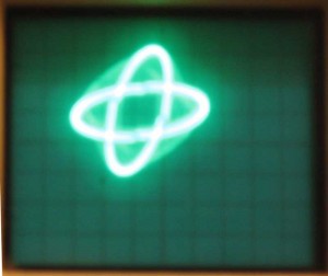
RTTY tuning in the old days was enhanced by hooking an oscilloscope in XY mode to the oscilloscope output of the ST-6. I have done the same with this test stream and think I have a pretty good pattern.

RTTY eye pattern

RTTY eye pattern

Getting the HAL ST-6 up and running wasn’t trouble free. At first, the output of the 170 Hertz filter/limiter wasn’t working at all. It took quite a bit of debugging before I discovered that a potentiometer case was shorted against the windings of a coil. While debugging this issue, I found and repaired a broken wire on another coil. I also tweaked the “alignment” and spent considerable time just checking out the circuit to make sure everything was working correctly. I also spent a lot of time chasing “issues” that turned out to be operator error, but I learned a lot in the process.

Once I get reception working well, and get a handle on how real operations work on HAM RTTY, I’ll start working on the transmit side of things. This HAL ST-6 has an audio FSK modulator incorporated in it. I’ll have to be cautious about how I bring it up, since AFSK operations are well known to have a lot a issues with harmonics and spurious noise.

SCELBI PCB update

Here’s a brief SCELBI project update. There were 16 different PCBs made by SCELBI for the 8H and 8B computers. The current status of my reproduction efforts of each of those cards follows.

Main System Cards – working reproductions of all 10 cards types have been completed
Reproduced
1100 CPU – 8H/8B
1101 Data bus buffer – 8H/8B
1102 Input – 8H/8B
1103 Backplane – 8H
1104 Front Panel – 8H/8B
1105 1K SRAM – 8H
1106 Memory Expansion – 8B
1107 4K SRAM – 8B
1108 Backplane – 8B
1109 PROM – 8B

Peripheral Cards – 1 reproduced, 1 in progress, 4 haven’t been started
Reproduced
2104 Teletype interface*

In progress
2103 Audio Tape read

Not started
2105 Keyboard
2100 Oscilloscope digital**
2101 Oscilloscope analog
2102 Audio Tape output

* not as high as normal vector boards
** double width vector board

A pretty conservative estimate is that I’ll have cassette interface read and write cards completed and working in the first half of 2015. I’m kind of hoping I’ll have them going by VCF east, but I’m not committing myself to it. I’d like to complete the Oscilloscope and Keyboard interfaces by the end of 2015. It’s really hard to say if I’ll actually finish them by the time the year 2016, comes around.

Apple PROM board, MEA/Apple TTY emulation update

The SCELBI PROM board is working fine and I was able to create a small program in the editor and execute pass one of the assembler with MEA. I can’t completely assemble a program and run it until I get the cassette interface built and operating. Pass two of the assembler writes the output to cassette tape. I’ll have to hold up doing a video until I can get the complete package going. My impressions of the MEA package are quite positive. It’s not as elegant as later software you might be more used to. However, considering the time frame it was made and the platform is the 8008, it’s a pretty nice package.

SCELBI PROM and extra SRAM boards cost $50 each and are available now. This recent work also confirms that the TTY board is working fine and those are available for $30.

I’ve been using an Apple IIe in 80 column mode with a bit-banged serial serial card to act as TTY emulator. However there are a couple of fairly significant issues that need to be solved before publishing this teletype replacement solution. It’s usable for me, but there are some problems. The two issues with my current Apple II TTY emulation solution are:

  • 1)The Apple II isn’t fast enough to scroll it’s screen at the same time it’s receiving data in a bit banged mode. It drops a few bits from the next character while scrolling the screen. This means that I’ll need to come up with a special designed card to support 110baud current loop with a UART. Since I’m doing a new card, I’ll consider figuring out how to add paper tape support and possibly printer support, as well.
  • 2) In 80 column mode, the screen driver doesn’t support carriage return, without also doing a line feed. In other words, you can’t move the cursor backwards to position 0 on the same line, like a real TTY would when it receives a CR. I’ll have to look into a software fix for this, but it might take sending the cursor to home and then moving it back down to the correct position on the page or something like that.
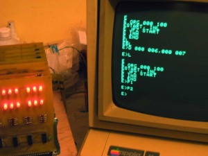
  • SCELBI running MEA

    SCELBI running MEA

    This image shows the Apple IIe acting as a TTY for the SCLEBI 8B on the left. The screen contains a small program entered with the MEA editor. The listing of the program at the top of the screen has two extra lines at the end. The “D 000 006,000 007” is an editor command that deletes lines 6 and 7. The “L” command lists the text buffer. The last two commands “P1” and “P2” are pass 1 and pass 2 of the assembler. Pass 1 shows no errors. Pass 2 writes results to cassette tape. Since the cassette isn’t installed in my system it actually does nothing. If I had a tape, pass 3 would read the object back into the system so it could be executed.

    The “E”s on the left side of the screen should be the first character of the next line, but the Apple IIe can’t scroll fast enough to be ready to receive the first character of the new line, so it receives a partial character.

    yeah – MEA running on reproduction SCELBI 8B

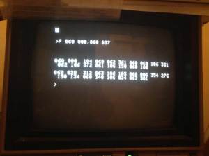
    MEA dump memory command - Apple IIe used as TTY emulator connected to reproduction SCELBI 8B

    MEA dump memory command – Apple IIe used as TTY emulator connected to reproduction SCELBI 8B

    Here is the dump of memory from the SCELBI PROM card from addresses 060-000 to 0600-037 as displayed on a 40 column Apple IIe, running some very simple TTY emulation software.

    To interface to the SCELBI, I’m using an Apple IIe with an old serial interface card. The Apple Serial Card is the first serial card released by Apple, and was intended to connect to serial printers. It included support for current loop and 110 baud rate. It’s the only thing I own, that supports that combination of baud rates and interface protocols. Be aware that this card is not the same as the very common Apple Super Serial card, which does not support current loop.

    For TTY terminal emulation purposes, I’m doing a major rewrite to the driver, as the default printer driver is not suitable for TTY emulation. I’ll post the emulation software and directions on connecting this serial card to the SCELBI TTY card as soon as I clean up a number of small issues.

    More updates on this exciting development to come soon.

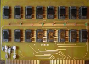
    SCELBI PROM Board Progress

    SCELBI PROM Board

    SCELBI PROM Board

    The PROM Board is built, installed and appears to be running. However, it’s not completely checked out. I need to hack together a simple Apple IIe TTY emulation program that will work with Apple’s old serial card. That card is the only card that I have (outside of my SCELBI stuff) that will run at 110 baud, but it was designed for printing, so I couldn’t find any ready made terminal program for it. The standard PROMs on the SCELBI 8B assume either a keyboard/oscilloscope interface or a TTY interface at 110 baud. Since we don’t have the keyboard/oscilloscope software, I burnt the TTY software into PROMs.

    It should take me a day to two to complete the TTY/terminal program hack for the Apple II, at which point, I will probably make short video showing the capabilities of the SCELBI 8B minus the cassette interface.

    I used black tape to cover the windows on the EPROMs because I’m told that sunlight will erase them after a while.

    Meanwhile, you can run the software in my OS/X emulator by downloading the MEA hex file from scelbi.com and jumping to 060-000. In a quick trial, it appeared to work ok for me. Be aware that I don’t currently have the cassette interface emulated, so cassette operations will not work. Cassette emulation is one the things on my to do list.