Mike's Super D'Lux, Apple ][ Forever, Home Brew,
Focal Plane, Shutter Tester
I retain copyrights to this site and this design, so anyone attempting
to reproduce this design for other than personal purposes, should
contact me first.
See my Optical Timer/Counter
page for my latest micro-controller based shutter tester design.
After far too many hours of experimentation (just ask my family), I think
I've come up with a quality shutter tester design. You should be
able to build your own Super D'Lux Home Brew Shutter tester for under 100
dollars. Keep in mind that complete Apple ][ systems can easily be
found for less than $50 on ebay and less, elsewhere. Presented here
is the fundamental design information and the software required. As
time becomes available, I'll be adding more details.
The light detector design is based on a fairly sophisticated cascode circuit
feeding a comparator. A couple of other designs were tried and abandoned
to due slow signal transitions. Using current limiting resistors
or even a current source, resulted in a rise/fall times of several hundred
micro seconds. Several hundred micro seconds rise time creates real
problems in accuracy at high shutter speeds, since 1/1000 is an exposure
of only 1000 micro seconds.
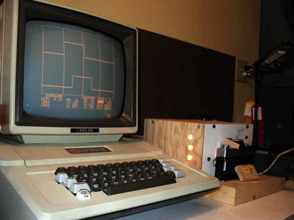
The prototype Super D'Lux was built on a proto board and plugs into a
slot on an antique, but working Apple II computer. Apple ][ specific
proto boards are hard to come by, but I understand proto boards designed
for IBM XT's can be cut down and adapted for Apple ][s. The
bus interface is very simple and could easily be adapted to other micro
computers. In fact the Apple ][ comes with a couple of TTL inputs
in the game port that could be used without any additional interface circuitry.
However you still need to find a place to hold the rest of circuitry
and the software will have to be adjusted to match your design. In the end,
I decided to build the first Super D'Lux on a proto board.
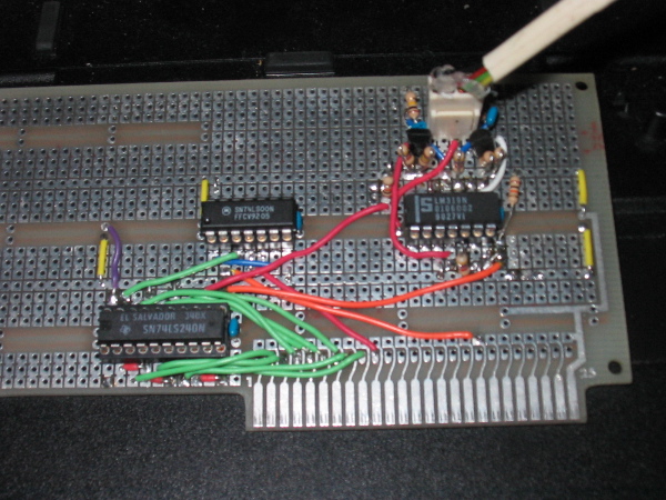
The first prototype was built on a proto board that I recently bought
on Ebay for about $8.
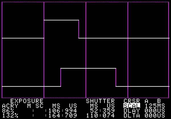
Super D'Lux software directly samples the detector, times the shutters
and displays the results in text and graphical formats. It even
will estimate shutter accuracy for you, automagically. Maximum measured
exposure is about 4 minutes. Minimum is under 1/1000 second. Maximum
shutter travel time between the two sensors is about 1 second. If
you choose to utilize another kind of computer you will have to port
the software and adjust the timing.
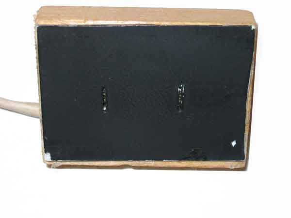
Detector
My detector is a block of wood with the two photo transistors mounted
inside exactly 18mm apart. In front of the detectors is a piece
of styrene plastic with two slits in front of the photo transistors. The
slits were created by heating up a chisel shaped exacto blade and
running it through the plastic. The plastic is painted black to
minimize reflections within the detector. On the surface this component
looks very simple. However you must be as precise as possible when
creating this unit. The accuracy of the shutter tester is more dependent
upon this component than all others combined.
You should use a variable light source in conjunction with the shutter
tester. A home made meter tester, with variable brightness capability,
can be seen on my tools page. Adjust the light to the minimum level
that still registers exposures at medium and fast shutter speeds.
Using more light than necessary will probably result in exposure readings
that are higher than actual, because ot scattered and reflected light switching
on the photo transistors too soon and a delay in turn off.
Design and construction of the photo detector is critical for accuracy
at high speeds. If you are having trouble adjusting the high speeds
on your camera, when using your home made shutter tester, it could be that
your detector needs work. See the bottom of this page for more information
pertaining to the accuracy any shutter tester.
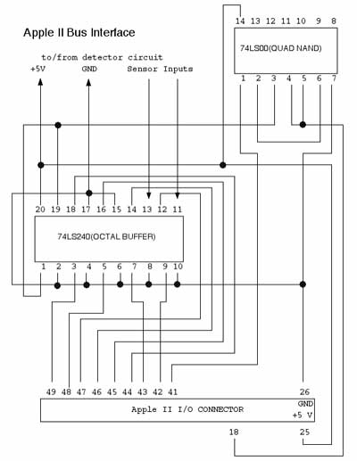
Hardware Circuit
Here is the hardware schematics for the Apple ][ bus interface. One
reason why I choose the Apple ][ was that interfacing to this bus is trivial.
For instance, adding latched outputs to this interface only requires
one more chip, should you need them. If you choose to use a different
processor, such as a PIC or Commodore 64, you will have to replace this
circuit with an appropriate design for your processor. As mentioned,
the game port on an Apple ][ has 2 ttl inputs that could be used instead,
but you will still have to find a place to mount the rest of the circuit
and the software will have to be adjusted accordingly.
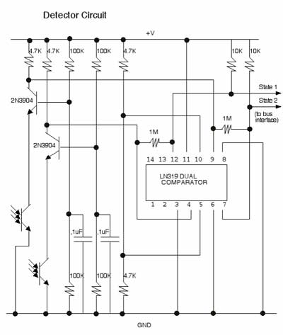
Here is the schematic for the detector circuit. I believe inclusion
of the LM319 comparator is most likely overkill, but I have included it
because I was using it prior to the change to the cascode design. It
can probably be omitted completely or replaced with another comparator.
The 2N3904 can be replaced with a 2N2222 transistor, with little or
no measurable difference in performance. This transistor design is
called a cascode type circuit. The response time is a few micro seconds
for this detector, instead of several hundred for other designs that I tried.
One enhancement you may consider, is adding a variable resistor
in place of one of the 100K resistors in order to calibrate both sensors
to equal sensitivity. I have not found this necessary on my prototype.
Software
One reason for using the Apple II was simple programming model and the
existence of simulators that allowed software development on a Macintosh
running OS/X. I developed the software completely in a simulated environment
on my Macintosh using a program called Virtual ][. The assembly code
was developed using a free 6502 assembler called ACME. Apple ][ simulators
and 6502 assemblers exist for other platforms. You should be able
to download and run my shutter software on most any simulator you find.
You can use the simulators method for simulating the game push buttons,
to simulate shutters opening and closing of shutters, if you assemble the
machine code with the !set simulator flag turned on. This program
is hard coded to assume the board is mounted in slot 4. You can change
the "sensor = $c0c0 ;card
plugged in slot 4" line and reassemble to move the card elsewhere. I
don't feel it would be worth the effort to auto detect the slot and adjust
automatically.
Loading the software into an Apple ][ is quite simple if you have a
serial card in your Apple. There is much data elsewhere on the web
on how to move programs onto an Apple ][. However, one thing you
must be aware of is that you must POKE 17408,0: POKE 104,68 and type "NEW"
prior to downloading the basic program into the system or the program
will not run correctly after it is downloaded. Once the basic program
is loaded into your Apple ][, save it to disk with the "SAVE SHUTTER" command.
The assembly code is loaded at $4000 and has a length of $400. Once
loaded into the system save it to floppy disk by typing "BSAVE ROM,A$4000,L$400.
The basic program will load it automatically when it starts running.
One last thing. Proper timing is dependent upon a careful
analysis of CPU cycles used by each instruction in the assembly source.
It is based on use of a Apple ][ running a standard 6502 at 1.023
MHZ. If you are running a different clock speed or processor variation,
the reported timing may be off. Timing on the simulated version
will also be off, because of the different method used to sample the game
input switches. This can be corrected through careful analysis of
the actual processor clock speed and clock cycles used by each instruction.
The adjustments are taken care of in lines 1111 through
1129 and on line 10020 of the basic program. As designed, the software
will sample the inputs every 16 micro seconds, which is around 64,000 samples
per second. This provides 64 samples for 1/1000 exposure, providing
accuracy of better than 5%. At higher shutter speeds, accuracy will
suffer accordingly.
Basic
source code is found here.
Assembly
source code is found here.
Machine
code - not for simulator
The Supr Shutter Tester on a Real PC Board!
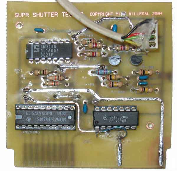
I was so proud of my design that I had to replicate it on a custom
PCB. I have never gone to the effort of making a PCB, on any previous
project, and this was a fun learning experience. It is made using
the laser printer/photo paper/iron technique described on a number of web
sites. Apple expansion cards require a double sided design with a card
edge connector, which seriously complicates construction. I drilled
the holes all by hand with a pin vice using either a #60 or #70 (vias and
transistors) bit. The result is not real pretty, and the layout
has one mistake that I had to correct by cutting a trace, lifting a pin
and running a jumper wire, but it works. Corrected artwork is available
in postscript format upon request.
Accuracy Issues
The performance of an electronic shutter tester is dependent upon
a number of factors. Let's consider some of these factors, using an
real world example at a shutter speed of 1/1000.
- Velocity of Shutter. This can be calculated by dividing curtain
travel time by distance. The horizontal travel curtain in Minolta
SRT 101 should be adjusted to cross the 36mm focal plane in 13.5 to 14 milliseconds.
Lets assume 14 milliseconds and divide by the distance of 36mm. The
result is 14milliseconds/36mm = .38889 milliseconds per millimeter.
- The time between the opening of and the closing of the shutter.
This should be equivalent to the shutter speed, in our example is 1/1000th
of a second or 1 millisecond.
- Combining the velocity with the exposure will result in the distance
between the opening and closing shutter curtains which in our case is 1millisecond/.38889milliseconds/mm
= 2.57mm.
- Now consider the size of the photo transistors or other electronic
sensors that is needed to switch the circuit on and off. Assume
the detector is 1mm across. For a 1/1000 or 1 millisecond exposure,
the detectors relationship to the opening between the opening and closing
shutter is 1mm/2.57mm or 37 percent. It should be clear that
a smaller sensor is better than a larger sensor.
- Phototransistors have a lag time between being switch on and or off
and visa versa . Each particular phototransistor design is different
in this regard, but it is easy to find off the shelf photo-transistors
that have a lag time of 10 micro seconds or less. This response
time is similar in both turn on and turn off functions, so basically cancels
itself out. This fast response time and the fact that it is pretty
much symmetrical for turn off and on should result in only small error.
- Phototransistors and other photoelectric devices in a real
world circuit don't instantaneously turn on or off the moment a single
ray of light touches the sensor. Phototransistors have a curve that
allows more current to flow as more light reaches the sensor, at least until
it is saturated. As the opening curtain travels across the focal
plane, it allows more and more of the light to reach the sensor, which in
turn, allows more current to flow, until enough light reaches the sensor
to saturate it. The circuit in which the phototransistor is placed
will switch on after a predetermined amount of current flows. Bottom
line is that the circuit turns on sometime after light begins hitting the
phototransistor, not immediately. The circuit turn on point depends
on both light intensity and the circuit in which the photo transistor is
placed.
- There is a similar lag time for turn off of the circuit. A
properly designed circuit will turn off in a inverse function compared to
the turn on. If this is the case, the lag for turn on and turn off
will mostly cancel each other out.
An analysis of these factors reveals that to minimize error, one item is
the most critical, assuming that the sensor designed is as small as practical.
- Symmetrical electronic turn-off/turn-on performance.
In other words, it is most important that the function that turns on the
sensor output is as close as possible to the function that turns it off.
Back to Mike's Hobby Home Page