SRT Meter Tune-up Notes
Disclaimer
I will not be held responsible for any damage that results from you
looking at or following these notes. If you don't feel comfortable goofing
around with this stuff or the possibility that you could damage something
on your camera, just don't do it.
Overview
These adjustments assume correctly operating meter components. There
are a number of common problems with Minolta SRT meters. This page does
not currently address these ailments. I may be addressing some of
these issues on the SRT repair pages in the future. The most common
problems you might encounter are:
- A stuck needle - the needle may stick to the old and sticky foam
that was used in construction.
- CDS sensors that come loose from the viewfinder prism - they must
be reglued with clear glue.
- Strings that have come loose - must be restrung.
- Stuck electronic switches - locate and correct.
- Shorts or opens - locate and correct.
Also I highly recomend that you use a variable light source for calibration.
A brief description of the one I made can be found on this page SRT meter adjustments
The SRT meter has two adjustable components. One is the electronic
circuit that controls the needle in the finder. The adjustment for the
electronic portion is easily reached by removing the bottom cover of the
camera. The other adjustment is the mechanical mechanism that controls
the circle in the finder. This adjustment is a bit harder to reach as the
top cover of the camera must be removed. With this information and a good
understanding of the operation of the circuit detailed in the understanding
operation section, you should be able to fine tune your meter to provide
best possible performance in all light conditions.
Electrical Adjustment
Remove the two screws holding the bottom cover to the chassis. Remove
the bottom cover. There will be two variable resistors visible. The
one to the rear of the chassis adjusts the battery check function. The
one towards the front of the chassis (with the green and red wires) adjusts
the meter. The resistors should be adjusted by moving them with carefully
with a wood skewer. Adjust the meter first, and then the battery check
function afterwords. Use a constant light source for checking out the
meter by comparing to a known good camera or meter. I built a light
box for this purpose. See the basic design described on my tools page.
Mechanical Adjustment
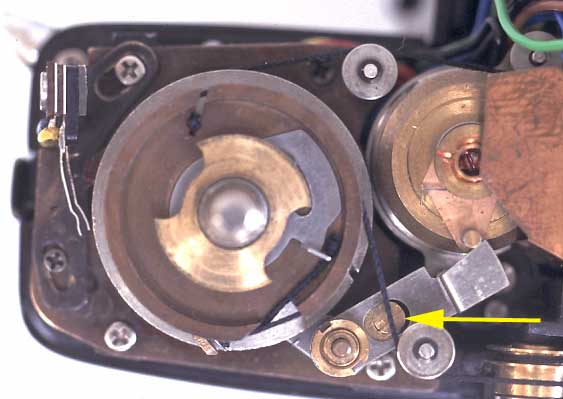
The other meter adjustment on the SRT series of cameras is
a mechanical one. This is located under the top cover of the camera just
to one side of the viewfinder. See my disassembly section for notes on
how to remove the top cover. In this picture, the adjustment screw is
indicated by the yellow arrow. Using this adjustment, the circle (needle
follower) in the viewfinder can easily be adjusted up and down. This is
a linear adjustment and will affect all light conditions equally. For instance,
this adjustment can be used to help take care of a 1 stop underexposure
that is consistant in bright or dim light. Note that the service manual
recommends setting the circle at the top of the BC indicator in the view
finder when the camera is at EV 10, ASA 50. With my old camera's,
the meters cannot be calibrated with the circle set this way.
Combining mechanical and electronic adjustments
If your meter is way out of whack for some reason - reads right in
some conditions and wrong in others, you may have to adjust both the mechanical
and electronic settings. In order to do this efficiently, it is best
to follow a procedure something like this.
- Calibrate the electronic portion of the meter in a bright light.
Compare to calibrated camera or meter to ensure accuracy.
- Check the meter in dim light. Compare to calibrated camera or
meter.
- If the meter reads underexposure in this dim light, slightly decrease
the resistance of the adjustable resistor. Then go to step 6.
- Or, if the meter reads overexposure in this dim light, slightly
increase the resistance of the adjustable resistor. Then go to step
6.
- Or, if the meter read OK, you are done.
- Now check the meter in bright light again.
- Adjust the mechanical portion of the meter this time. Go to step
2.
Back to Mike's
Hobby Home Page