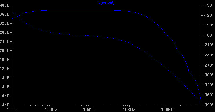
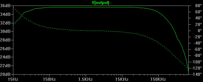
preamp in simple chassis

 3 Transistor Audio Preamp for a Dynamic Microphone

The first preamp I built from plans on the web had a couple of issues.   This included too much amplification which was causing clipping, even when the amplification was adjusted downward.  Also there was no filtering of frequencies above audio spectrum.  Finally the description of the circuit on the authors web page didn't really match actual behavior.   I decided I wanted to improve my preamp and that this would also be a good opportunity to learn how to use Spice hardware design tools, as well. The first attempt eliminated the 2nd stage amplifier, but that had some limitations detailed in the notes on my 2 transistor design (bottom of page).

Note that I am not a audio design engineer and accomplished this result after much trial and error using the Spice simulator tools. This three transistor design is the result of that effort.   I also tried some op-amp designs using the Spice simulator but found that low frequency response dropped off significantly more than with the transistor design.  Although there are many proponents of using op amps for pre-amp implementations, the Spice simulator really doesn't indicate that they will perform any better than a simple transistor design.

three tranistor mic preamp
This design is pretty close the the original. We don't need a lot of gain in the 2nd stage.  The resistors R4,R7 and R9 set the gain by dividing the output from Q1.  Increasing R7 and R4 reduce gain and increasing R9 increases it and visa versa.  Actual implementation uses a 10K pot in place of R7 and R9 in order to allow adjustable gain over a fairly wide range.  The 200uF CAP between emitter and ground on Q1 was removed because the SPICE simulator shows it tends to attenuate the lower going side of the output signal a bit.   Some other transistor and cap values are tweaked mostly because those are the values that I could find in my stash.  SPICE simulation shows that these changes have low to no impact on quality of output signal.

The preamp is designed to be powered by a 9 volt battery and only draws a few milliamp.  A typical Alkaline 500mAh battery should last 250 hours or more.  My current implementation is on a breadboard, but I may build one on a PCB in order to fit it in a small case in the future.

C4 is added to attenuate high frequencies as can be seen on the SPICE output shown below.
response curves
The solid line is gain in dB with a .005 volt peak to peak sine wave input.  It starts falling off below 100HZ and again above 30kHZ which includes the main audio frequency range.  The dotted line is phase shift.  Phase shift is not ideal but is fairly consistent in the main audio frequency range.

Here is the weak 2 transistor design

preamp schematic
This design uses the exact same front end as the original design.   I thought that that all the needed amplification could be accomplished by the first transistor and the second transistor wasn't necessary, so was omitted in this version.  The third transistor in that design was retained as driver for the line output.  I also added output filtering of high frequencies.   

While this design works, it turns out that amplification is not ideal with weak input signals.   The 2N3904 transistor doesn't have quite enough gain to provide a strong signal with very low input levels with just one stage of amplification.   I have reverted to a three transistor design shown at top of the page. 
performance
This graph is the output of the spice simulator.  It shows pretty flat amplification from around 30Hz up to about 100kHz, at which point the high frequency filter kicks in.  Also phase shift (dotted line) is pretty constant in the audio frequency band.

If you have suggestions, please feel free to contact me.


Back to Mike's Hobby Home Page