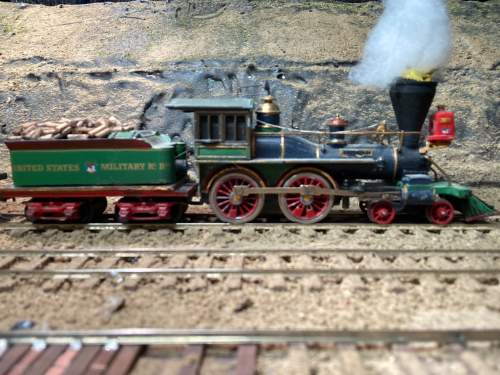
Remotoring the Mantua General
Part 2 - draw bar and drive shaft
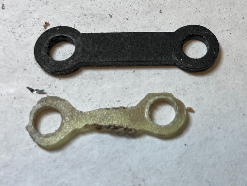
Drawbar
A shorter, more prototypical draw-bar can be easily cut out from a
piece of PCB stock. First mark and drill the two 9/64" holes
.5" apart. Then using various cutting tools, you can cut the
outside dogbone shape using the original drawbar as a template. I
use a small band saw, dremel cut-off disks and various files to shape
the draw-bar. Make sure that the PCB copper layer is cut so that
there will be no connectivity between the locomotive and the tender
through the draw bar.
Drive Shaft Replacement
Materials required
- Guitar string .016" diameter (known as 016 music wire)
- 3/16" brass rod
- Hobbytown 100000K Universal Coupling Kit for 3/32" shaft
- ball
- socket for 3/32" shaft
- square drive rod
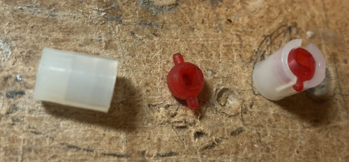
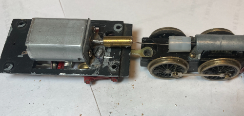
The Hobbytown 3/32" universal joint will fit perfectly onto the
Mantua/Tyco locomotive drive shaft. The square drive rod is cut
short and a small hole drilled to accept the music wire which is
soldered in place. It is a bit tricky to get a perfectly centered
hole, but if the hole is slightly oversize, the wire can be centered as it is soldered in place.
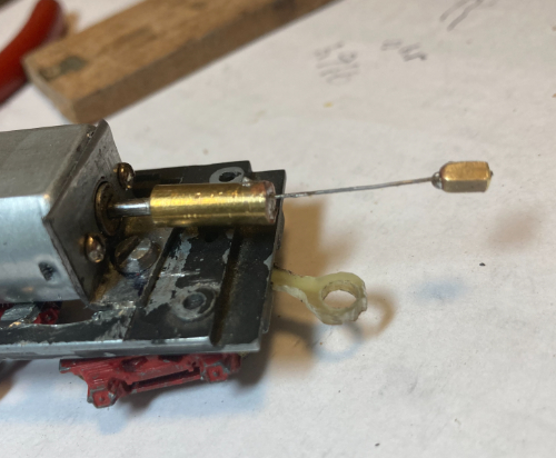
Adjust the length of the wire so it reaches from the drive shaft to just
short of the motor when the locomotive is coupled to the tender.
The motor end of the drive wire is soldered into a slightly oversized
hole drilled into the the center of a piece of 3/16" rod. I used a
#73 drill bit to drill this hole which is .024", .08" larger than the
music wire that I am using. The other end of the rod is drilled
with a 2mm hole to fit the drive shaft of the motor. After
soldering the wire into the rod, the rod is superglued onto the 2mm
shaft of the motor.
The hard part is now done. On the next page, I'll show how the DCC decoder is wired.
Back to Mike's
Hobby Home Page