Model Turntable Construction
This page is intended to at least partially document how I scratch
built a model of the City Point turntable for my City Point Terminal
model railroad.
Research
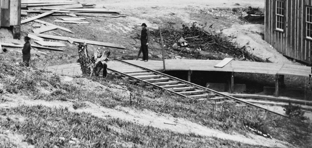
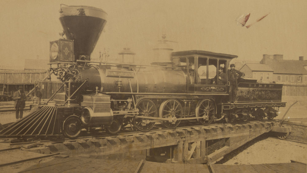
The first step was to gather all the images that I could find of
this turntable and similar ones built by the USMRR. I have
found two real useful images of the turntable at City Point.
I believe high resolution versions of all of these images can be
downloaded at no cost from the Library of Congress.
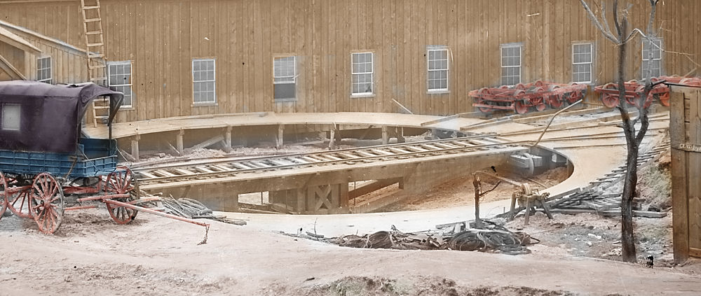
I had created a colorized version of this image a number of years
ago.
There are several additional images with some
aspect of the turntable in the scene, but they are of marginal
usefulness to the modeler.
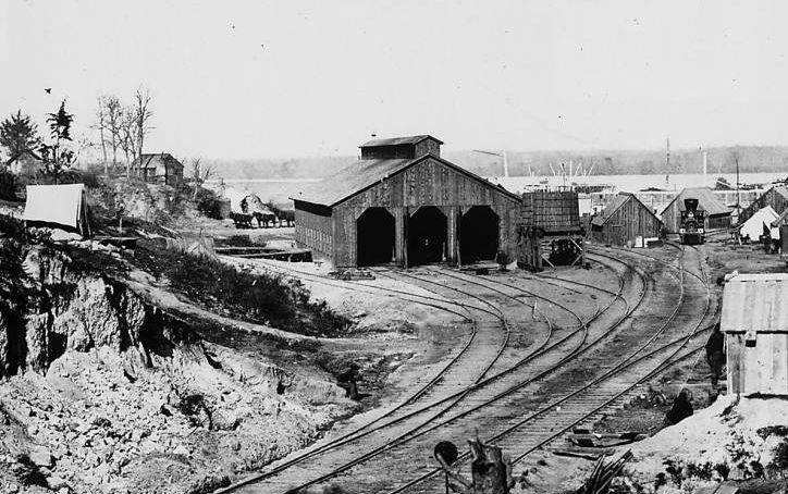
Here is an example where the turntable shows up in the image, but
not much in the way of details can be seen.
Bernard Kempinski found an image with a very similar turntable and
documented it on
his blog. You can search his blog for the keyword
"turntable" and find a number of useful articles. This
turntable differs in a couple of ways from the one at City Point,
but otherwise provides good detail. Two obvious differences
is that this one does not have a walk along the track and the
sides of the pit are framed.
The next step for me was to decide how to
approach constructing a model.
Mechanical Construction
Even though the historical City Point railroad
was manually operated, the idea of motorizing this turntable was a
no brainer for me. A number of years back I had built a
stepper motor controller for a barn
door sky tracker. This was supposed to be used to take
long exposure pictures of the night sky. I only used the
barn door tracker once. Years ago, I disassembled it
to use the motor to turn a rotating display that I used in a
vintage computer exhibit. I thought that operating a model
railroad would be a much better application for this motor.
The rotating display used a automobile wheel hub that I had
purchased off of eBay as the base and I figured that I could reuse
the hub as the pivot point for the turntable.
I decided to start with building the movable
bridge first and made an elevation view with an illustration
program. I did this in 1/87 scale so that I could print it
out and build the side frames directly on the drawing.
Before making the bridge itself, I made the trucks for the
wheels. I made these before the bridge side frames because the
ends of the stringers/joists meet up with these trucks in a very
specific wa. It would be easier to get rest of the model
right, if I already had the trucks built. I made the wheels
from from a couple of freight car wheel sets that were cut in
half. The trucks have semi-circular groves cut in the bottom
to hold the axles. The wheels are affixed to the frames with
brass strips attached at the center of the bottom. The flange
on each wheel was also ground off in order to give me a little more
room for error in putting down the rail. The wheels are easy
to slide off the ends of the frames, so I can upgrade them to the
spoked type seen in the pictures at a later time.
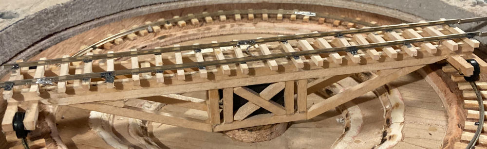
Next, I built the side frames for the
bridge. As I was cutting and gluing together the scale
lumber for the side frames, I noticed the joist/stringer at
the top was supposed to be doubled. I had to undo some of my
work to get this part of the model correct. The Northeastern
Scale Lumber was cut with a Micro-Mart chopper and glued together
with Titebond wood glue. Many pieces were trimmed to final
size with a Dremel type tool with a cut off disc installed.
After the two side frames were built, I joined them together with
additional pieces of lumber, making sure the spacing exactly
matched HO scale track spacing. I noticed long ago that the
stringers/joists on wooden railroad bridgework is designed to
support the rails in as direct a way as possible.
After joining the two sides, I noticed that the bridge was twisted
slightly. If not fixed, this would be a big problem as the
tracks on both ends had to be level or they wouldn't line up with
the lead in tracks when the turntable was rotated. I had not
yet installed the ties or track, so the remedy was easier than it
otherwise would have been. I loosened a couple of the key
joints and soaked the whole bridge with water and reglued the
loosened joints with the bridge clamped upside down on a level
surface. It still wasn't perfect after this effort, but I
figured that if it wasn't good enough, I could have another go at
it, later on.
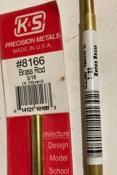
By now, I had discovered in my stash, some 3/16" OD brass rod and a
matching 7/32" OD brass tube. It turns out that this brass rod
fits perfectly in the tube with almost no slop. I could use the
brass rod as the drive shaft for the bridge and the tube as the
bearing. This worked very well and I never did make use of the
automobile hub. Anybody want a very lightly used GM wheel hub?
At this point I decided to put a block of hardwood in the center of
the bridge to act as the support for the rod that I was going to use
to turn the bridge. I cut the block to size and painted it
black to minimize it's visibility before gluing it into place.
Now, I had to execute one of the most exacting operations of this
entire project. I needed to find the exact center of the
bridge (the center between all four wheels) and drill a 3/16" hole
for the drive rod that was exactly 90 degrees to the span of the
bridge. I did this, inserted the brass rod and found it seemed
reasonably close to ideal. I would find out more only after I
completed the pit. I drilled a hole into the side of the block
through to the center drive rod hole. This would to allow me
to add a wood screw that could be used to lock the drive rod and
prevent it from slipping.
Note that this bridge is surprisingly solid for such a small
model. I think the engineers that designed this structure back
in the day knew what they were doing. I put the bridge aside
and started work on the pit.
The pit is constructed on top of a square piece of 1/4" plywood
which acts as the base for everything, including the drive wheel and
stepper motor. I was afraid that the 1/4" thickness would not
be sufficiently stiff, but I think it will be fine, as most of
the base is reinforced by the 3 more layers that make up the pit.
The pit is made of 3 circles of 1/4" plywood, all with the same
outside diameter. A hole is cut in the center of each, with
smaller sized holes as you go down into the pit. Inner
dimensions are not critical, as this area will be modeled as dirt
and sand when I get to adding the scenic details. The
outside circles were cut on a band saw with a simple circle cutting
jig. The inside circles were cut freehand, following a line
drawn with a compass. The top inside edge of each circle was
rounded off with a router, which should help make the dirt/sand
effect a bit easier to model. Outside dimensions were chosen
to provide room for the guide rail and the walking platform that I
haven't yet modeled. The center point of the pit received a
small disc of 1/4" plywood. I figured that this would be used
to hold the drive rod bearing and would be mostly covered by model
sand and dirt when that was added.
The center point received a 7/16" hole in order to hold a piece of
the bearing tube. I tried to make this as close to 90 degrees
as possible as any deviance would cause the bridge to oscillate as
it rotated. Having a drill press helped with this alignment.
Once the pit was glued up, I used the center hole and a compass to
make a line to match the exact distance from the center point of the
bridge to the wheels. Note that this isn't the same as the
distance to the end of the bridge. Geometry comes into play
here and makes the wheels a slightly different distance from the
center than the end of the bridge. I glued down some shortened
ties centered on this line.
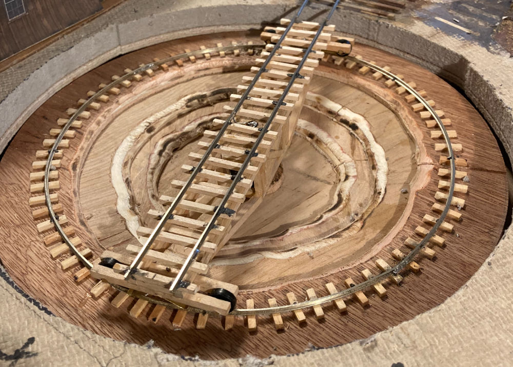
Finally, I bent a piece of rail into a circle as best I could.
I spiked the rail down, using the bridge with it's drive rod
inserted into the bearing as a guide. It took a lot of
tweaking to get the wheels to follow the rail correctly. I
eventually had to shim in a very small piece of extra rail in order
to make the diameter of the circle a hair larger than I originally
had it. Circumference = 2 x radius x PI works only if you
measure radius correctly.
At this point, I could check the level of the bridge as it
rotated. It turns out that it was off a little bit. I
decided to ream out the hole for the drive rod in the bridge just a
bit and then using the slop that was now available, glue the drive
rod into correct alignment.
Next I had to fabricate a drive wheel and drive band so the stepper
motor could actually move the bridge.
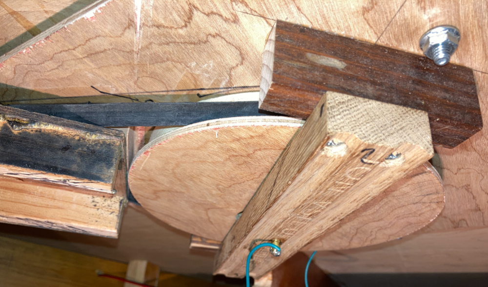
The drive wheel is made up of two circles of wood. A 3/4" piece of
pine, is cut with a diameter of 6.75 inches. Glued to that is
a 1/4" inch piece of plywood cut slightly larger, about 7.25" in
diameter. The idea is that the larger diameter piece keeps the
drive belt from slipping off. After they are glued together, a
3/16" hole for the drive rod is drilled in the center. A two
inch hole is drilled close to the center so a locking screw can be
screwed into the center to hold the drive wheel solidly to the drive
rod. Finally a couple of brackets and a cross member are cut
that will provide a second bearing point for the drive rod.
The cross member will also keep the drive wheel from falling
off. The cross member is screwed into place, but not glued so
that it can be removed, if necessary. Note that the drive band
can't be removed without first removing the cross member.
The 7/32" hole for the bearing is drilled on a drill press with the
cross member screwed into position in order to make the hole as
close to 90 degrees to the plane of the pit as possible.
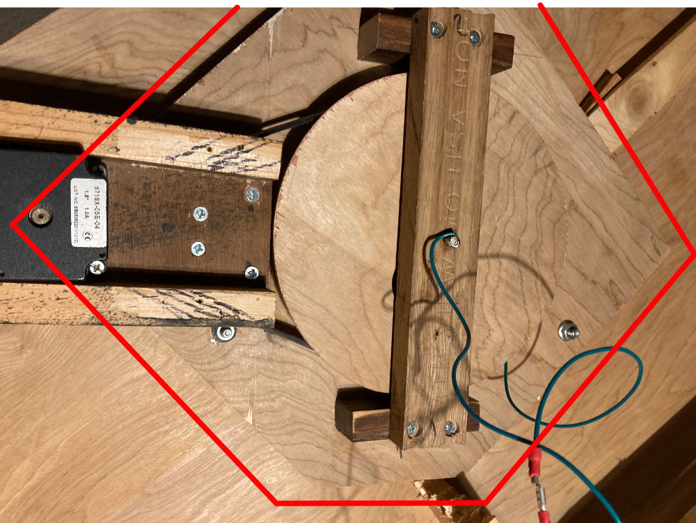
The stepper motor bracket, which is the same one that was originally
used on the barn door tracker, is attached to the pit base with
screws to allow for maintenance.
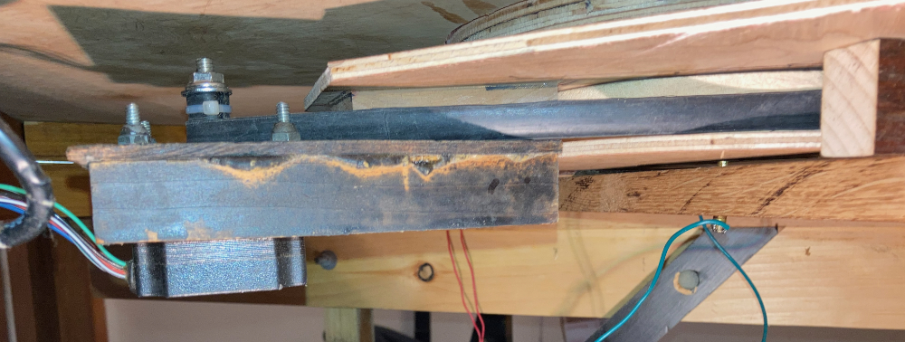
The drive band was cut using a scissors from a bicycle inner
tube. After estimating the needed length, it was glued using
contact cement and left to cure overnight. It's probably just
a bit too long, as it slips just a bit from time to time. At
some point I'll probably tweak the drive band length a bit.
The contact rubber on the drive wheel on the stepper motor was also
cut from an inner tube. As contact cement didn't seem to hold,
it was glued again with glue from a tire patch kit. I held the
rubber on the drive with a couple of small zip ties while the glue
dried. After it dried, I decided to leave the zip ties in
place.
The ties were glued to the bridge using wood glue. I used
epoxy to glue the rail to the ties rather than use spikes.
Even thought the bridge is fairly robust, it takes a lot of force to
spike track and I was afraid the act of spiking would damage the
structure.
At this point, a hole was cut in the top of the layout just larger
than the outside diameter of the pit. The dimensions aren't
critical, but I wanted to leave room for the walk. The
turntable is held in place with three bolts set in the top of the
layout and running down through matching holes drilled in the base
of the pit. It's not bolted down tight, but gravity holds the
unit in place. Nuts on the bolts can be screwed up or down to
fine tune the height of the turntable, so the turntable's rails
match the height of the rails on the rest of the layout. When
I do the scenery for the pit, I will probably lock everything down,
as going forward, I can service the turntable without removing it.
Rails were tested for length by manually rotating the turntable and
making sure that all four protruding rails are the exact same
distance from lead in tracks. I carefully ground the
ends of the long rails down with a Dremel tool to even them all
up.
Powering the Turntable
The part of this project that I enjoyed the most, was the
electronics and in some ways, this is also the easiest part for
me. I use a DCC system, but I think a lot of the principals
would be the same, no matter how you power your trains.
In order to power the locomotive on the bridge, you need to get
power to it. This must be done without running wires directly
to the track on the bridge as eventually they will get tangled, if
they are directly connected. I decided to use two parts of the
system that were already in place to get the power to the
bridge. The bridge can pick up one side of the DCC signal from
the circular track that runs around the pit and the other from the
brass drive rod. This is simple and effectively solves the
issue.
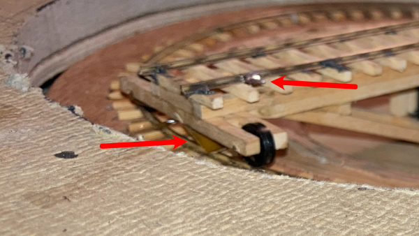
The drive rod part, was easy. I just plugged the bottom
bearing that was already in the bottom cross member and soldered one
pole of the DCC signal to that. You can see the wire running
to that in a previous picture on this page. A wire is soldered
from the top of the drive rod to one of the bridge tracks. At
this point, the connection from the drive rod to the drive bearing
seems quite reliable.
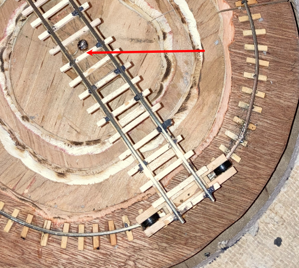
The pickup from the track was slightly more complicated. I could
have simply used metal wheel sets for pickup. The brass strips
that hold the wheels on, could have been simply connected to the
rail. Instead, I decided to attach wipers to bottom of the
trucks thinking that this may result in a more reliable
connection. I may change my mind in the future, but for now,
this is what I have done. By the time I add the walks around
the perimeter of the pit, these wipers will be almost invisible,
anyway. A hole is drilled through the bottom of the pit to
allow a feeder wire to reach the rail. This is the same
as how I connect power to the rest of the track ion the layout.
The last part of the electrical pickup problem was to prevent a
short when the locomotive moves from the bridge to the rest of the
layout. If you directly connect the bridge wiring to the
layout, only one end of the bridge rails will match polarity of the
lead in tracks. This is essentially the same problem as a
reverse loop.
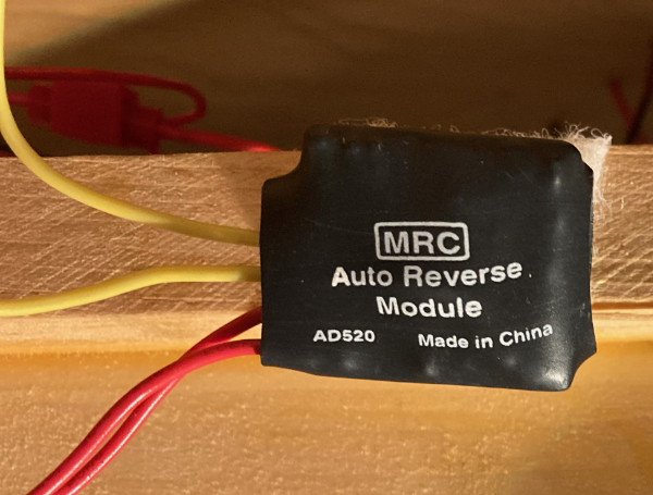
The solution to this problem was to install a MRC AD520 reverse loop
module between the feeders to the turntable and the rest of the
layout's track power. Fortunately, I had one of these auto
reversers left over from my last layout. I used spade type
connectors for this connection to allow for easier maintenance.
The Stepper Motor Controller
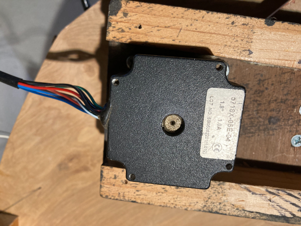
For the barn door tracker project I had purchased a NEMA size 23
stepper motor with a 1.8 degree step angle. This motor
is way overkill for the turntable application, but it was
already interfaced to my stepper motor controller, so I decided to
use it. Since I implemented half step control, I get 400 steps
per revolution of the motor. The additional belt drive
reduction of 21:1 gives about 8400 steps for a single complete
revolution of the turntable. This is more than enough
precision for this application.
I designed the stepper controller back in 2006 for the
aforementioned barn door tracker project. I'm not going into
the details of this stepper controller design here, but I'll
highlight some of the features and firmware changes that I made for
the turntable application. If you are interested in knowing
more details, let me know.
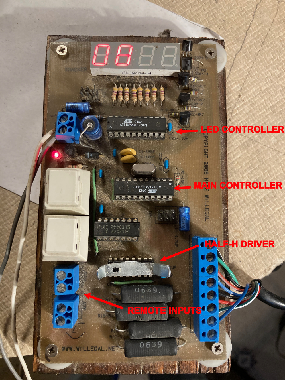
The heart of the design consists of two AVR ATTINY2313
micro-controllers and a TI SN754410 Quadruple Half-H driver
chip. It has a 4 character LED display, two on board key
switches and provisions for two remote inputs.
One of the AVRs has a very limited slave role and that is to drive
the LED display. It is connected to the main AVR through a
simple two wire serial connection, one wire for receiving commands
from the main AVR and a second wire to send responses to the main
AVR. The second response function has not been used.
This slave AVR receives commands from the main AVR which indicate
which four characters to display. The main AVR can also tell
the slave AVR to flash the displayed characters at different rates
or leave the display on, without flashing. The slave AVR has
no other capabilities.
The main AVR has the following functions.
- It sends display updates to the slave AVR whenever required
- It monitors the two on board key switches and the remote
inputs
- It maintains a 24 hour clock that holds current time in a
resolution of 1/10 millisecond
- It controls the stepper motor through outputs that connect to
the inputs of the TI Sn754410 Half-H motor driver chip.
The barn door was designed to be turned on and run for minutes at a
time as a picture of the sky was exposed on film. For the
original barn door application, the controller supported two
speeds. One was designed to allow the device to slowly track
the stars as the earth rotated. The other speed was a maximum
speed to rewind the barn door mechanism. It also
supported tweaking the speed as it tracked to adjust for the
slightly changing geometry as the barn door operated. There
was also a fine tuning calibration capability.
The requirements for a turntable application are quite
different. It only needs to run for a few minutes at a time
and needs real time operator control. The slave AVR display
driver firmware was not changed, but I ended up rewriting much
of the firmware of the main AVR.
This controller now supports 3 speeds, all of which are relatively
slow compared to the barn door rewind speed. Key switch
controls were changed to a very simple system. Pressing key
"A" causes the clockwise rotational speed of the turntable to
increase. Pressing key "B" causes the counter clockwise
rotational speed to increase. If you are moving in a clockwise
direction and want to slow down, you press the "B" key and visa
versa. Thus to rotate a locomotive that is on the turntable,
you press either key to start it moving. Then you can increase
the speed, up to two more times by typing the same key again or slow
it down or stop it by typing the other key. In practice,
operation is very simple and it is very easy to stop the turntable
so it is perfectly aligned with the lead tracks. This will
allow operators of the model railroad to mimic natural human
behavior. People will tend to slow down in order to attain
precise positioning of objects and speed up when precision is not
important.
I also added a set clock function. This is entered
automatically when the controller is powered up, or may be entered
by pressing both keys at the same time. Once in this mode,
pressing the "A" key will advance the hour and pressing the "B" key
will advance the minutes. Pressing both keys at once will exit
the clock set mode.
The old barn door application would display mode information when it
was not currently running. The display now always displays the
current time. Mode information can be deduced now by how fast
the display is flashing.
- If the controller is ready to go, but not moving the
turntable, the display does not flash.
- If the turntable is in motion, the display is set to flash
slowly
- If the set clock function is enabled, the display will flash
at a fast rate.
The remote inputs were originally designed to monitor limit switches
so the controller could stop the barn door when it reached either
end of it's allowed travel. The new firmware monitors these
inputs exactly the same as the on board key switches. One
remote input takes on the role of key "A" and the other key
"B". With this capability, I'll be able to add a secondary
turn table control panel to my layout. The plan is to add the
second control panel on the other side of this module, next to where
all the track switch controls are located.
Finally, since the slave display controller AVR never sends anything
back to the main AVR, I should be able to build one or more
additional slave clock displays by tapping into the signal going
from the main AVR to the display AVR and propagate it across my
layout.
Power consumption when not actually spinning the turntable is about
60 milliamps. When actively turning consumption goes up to
about 350 milliamps.
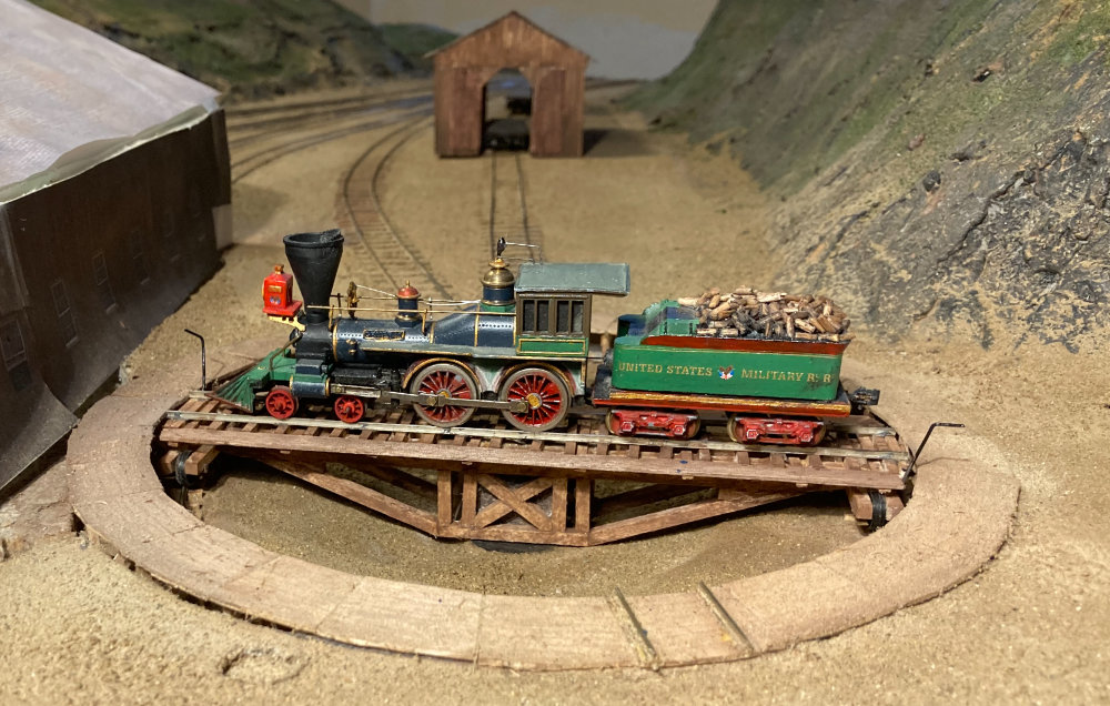
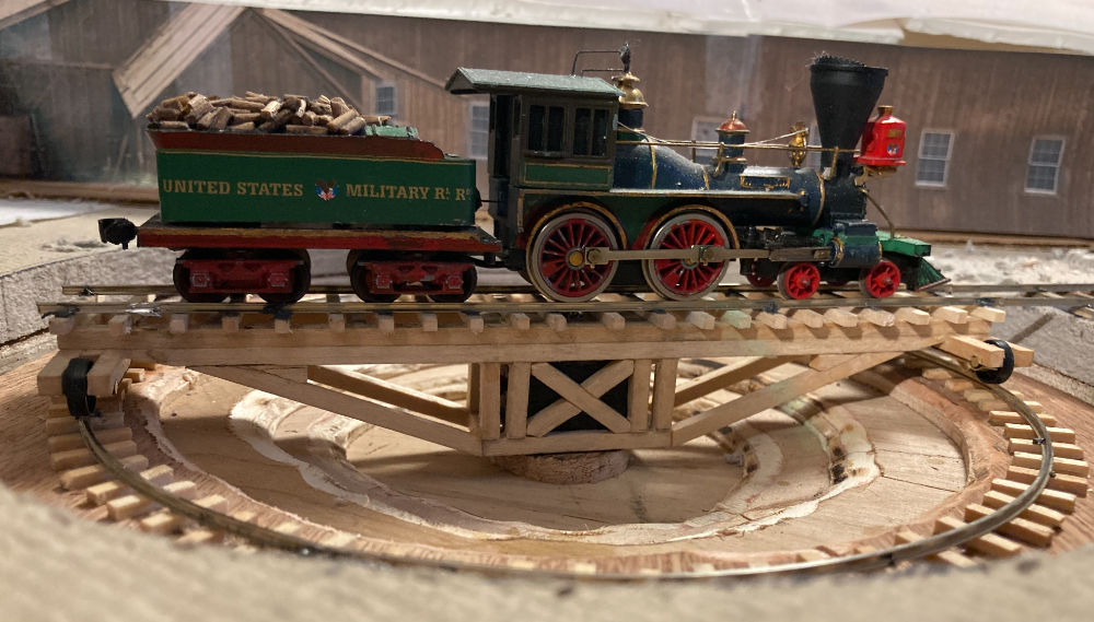
The Finished Turntable
If you have questions or comments, feel free to contact me at (mike@willegal.net)
Back to
Mike's Hobby Home Page