Model Railroad Switch Automation Hardware
This page documents how I automated switch operation my City Point Terminal model railroad.
This design is based on my locomotive automation hardware design.
Before reviewing this section, be sure that you are comfortable with my
locomotive automation hardware.
Totoise Switch Machine Hookup
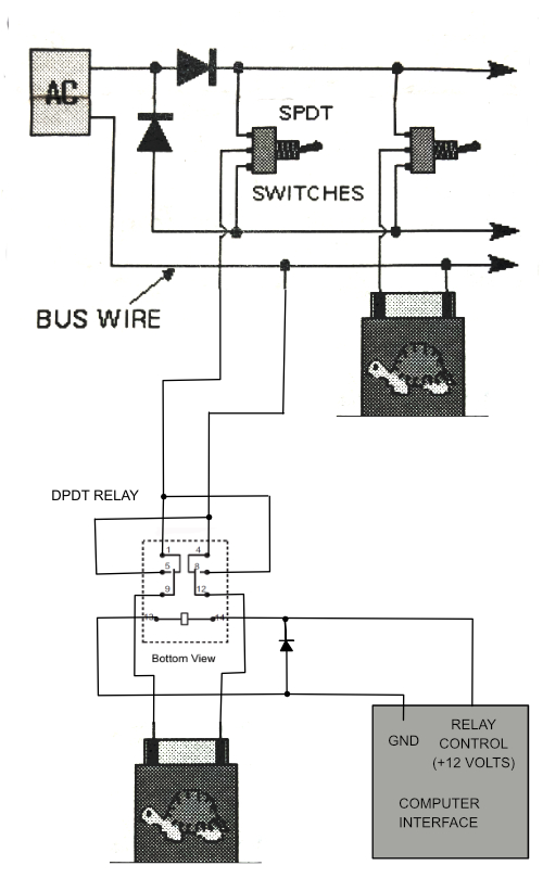
Tortoise Switch Machine Hookup (this drawing is an expanded version of the one found in the Tortoise instructions)
The Tortoise Switch Machine instructions show three ways to power
the switch machines. A long time ago I choose to use the AC power
method. This method uses an AC power supply with two diodes to
half wave rectify one side of the AC input into two signals, a positive,
a negative. The other output of the AC supply becomes the common.
The common is connected to one side of the switch machine power input.
The other power input connects to either the positive or negative
signal, depending upon the state of a single pole, double throw
switch.
In order to control by computer, I simply added a double pole, double
throw relay between the power inputs and the switch machine. When
the relay is activated, the switch machine power is reversed, which
causes the switch to change to the opposite setting. One bonus of
this type of configuration is that manual control without the computer
running remains working the same as it always has worked. Also,
manual override of the computer setting is built into the design, though
if the computer has activated a relay, manual control works opposite of
how it is supposed to.
One downside of this configuration is that for computer automation to
work correctly, the manual switches must be in a predetermined
setting. For purposes of my railroad, I simply set all switches to
go straight (not turn out) before starting the computer automation.
Controlling the Relay by Computer
The most complex part of this design is powering the relays.
Since I use an Apple II for automation and it has a relatively healthy
12 volt power supply built in, I decided to use relay's activated by a
12 volt signal. There are several important concerns regarding
using this approach.
- Since I decided to put the relays on the layout rather than in or
near the computer, there is a risk of shorts or other unexpected wiring
faults creating a fire risk. In order to reduce this risk, I
decided to add a fast acting fuse near the computer. The relays I
choose to use require about 16 milliamps each, so for the eight relays
that I am supporting per interface card, a 125 milliamp fuse should be
sufficient.
- The coil used to activate the relay stores energy and will want to
feed this energy back into the circuit when switched off. In
order to prevent unwanted voltage spikes , a diode is added across the
coil inputs.
- To further condition the computer 12 volt power supply, a couple of capacitors are added to the interface card.
Since I had room on the sense input board that I built and it already
included most of the address decoding I needed, I decided to add the
relay output circuit to it. The resulting schematic looks like
this, with the relay control output circuit highlighted.
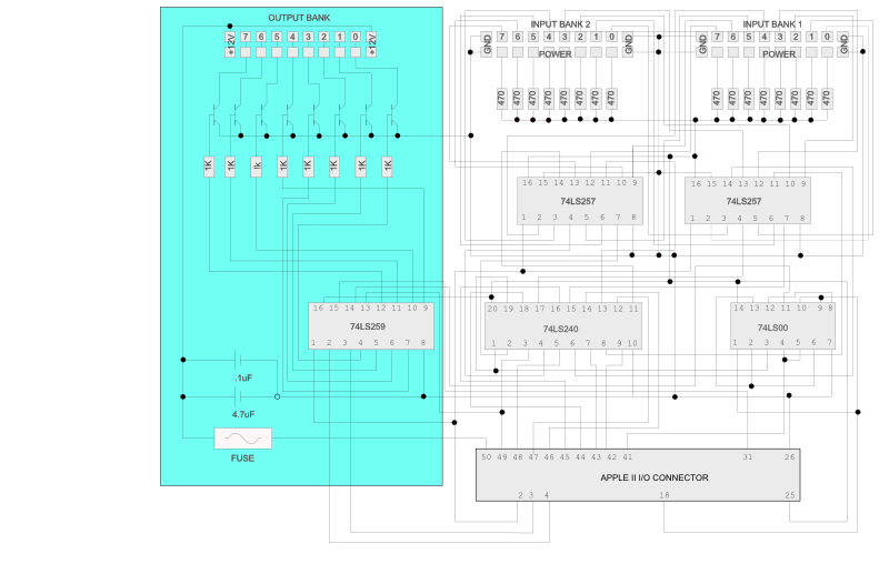
The circuit uses the eight TTL outputs of a 74LS259 type 8 bit
addressable latch to switch on a transistor that enables the 12 volt
supply to turn on the relay. The relay is mounted at the layout
near the tortoise switch. Addressing the outputs is easy. Write to
Apple II address 0xC0YX. Y is a value calculated by adding 8 to the
slot number. A card in slot 4 would be addressed with a C in the Y
position. X is a value between 0 and 7 and selects output
port. The least significant data bit is used to control the
relay. Use 0 to turn the relay off or 1 to turn the relay on.
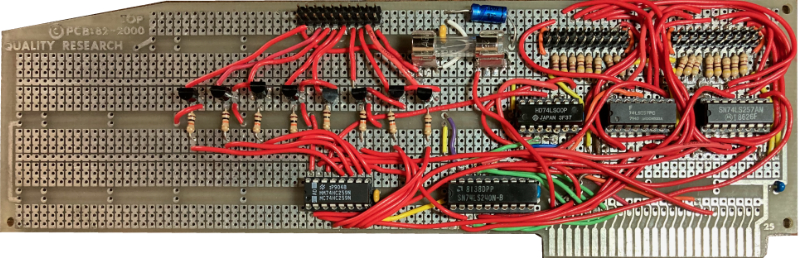
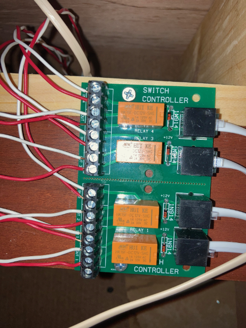
The modified interface board looks like this.
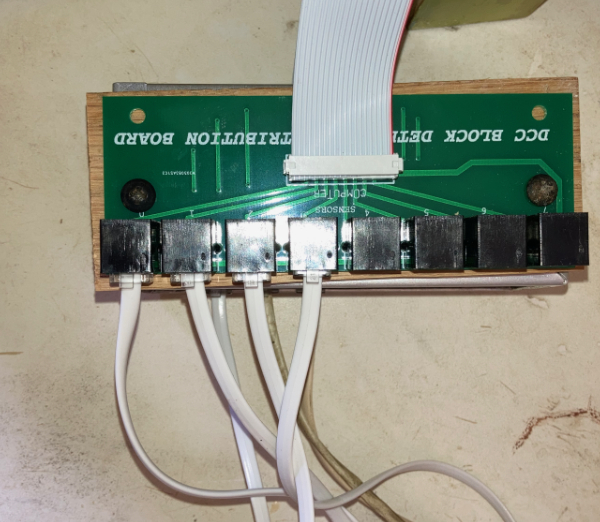
Connection Between Computer and Switch Machines on Layout
The connection between the computer and the switch machines utilizes
the exact same type distribution board and telephone cables as the
sensor circuit. The difference is that the distribution board and
the telephone cable carry the 12 volts needed to power the relays
instead of the current limited 5 volts and sense return needed for the
sensor circuit.
The final component of this system is a small board that holds the relay
and diode for up to four switches. Each switch has 2 pairs of
wires leading to this controller. One pair go directly to the
tortoise switch machine and the other pair go to the control panel on
the fascia of the layout. The telephone wires lead back to the
distribution panel which is located at the computer.
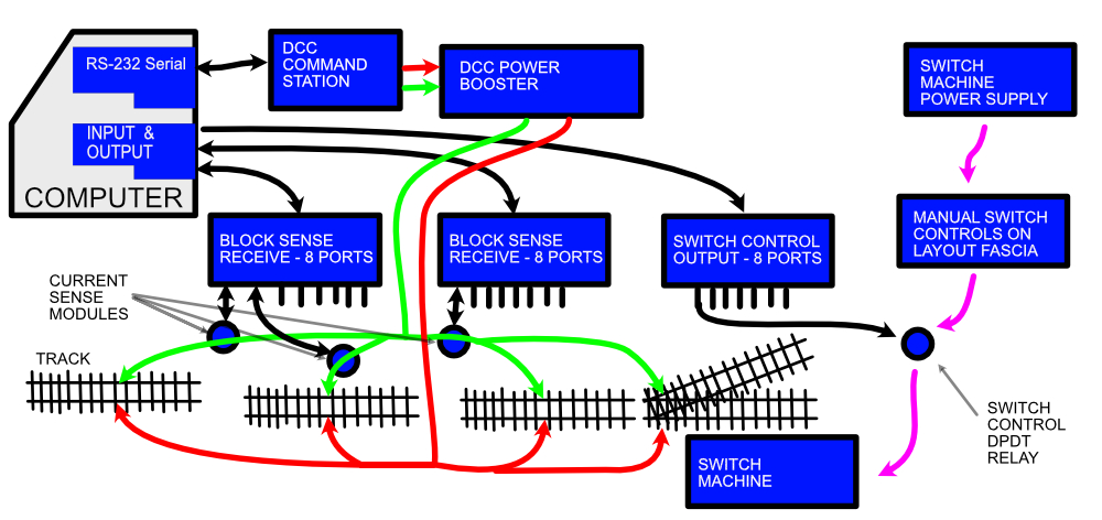
Overall Block Diagram of the Automation System Including Track Sense and Switch Control