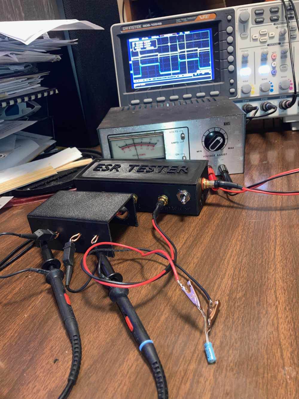
Once I built the chassis and installed the board and custom cables, I
proceeded to see if I could make sense of this device. This device
works by generating a small amplitude (~200 mV or ~35 mV) 100 kilohertz
square wave that is transmitted across a low resistance (10 ohms
or 2 ohms) to ground. The capacitor to be tested is added in
parallel with the resistors. The peak to peak amplitude of the
reduced square wave is then compared against the square wave prior to
adding the capacitor. The result is computed to be a percentage of
the original wave. A bad capacitor with high ESR will affect the
signal very little while a capacitor with low ESR will greatly attenuate
the signal when inserted in the circuit.
For example, the ESR tester is set up in 10 ohm mode. Without a capacitor in the circuit the signal has a 200mV amplitude.
Once the capacitor is added to the circuit, the result is a 24mV peak to peak signal.
The percentage is 24/200 or 12%. The ESR can then be determined by
consulting the following table, which is taken from the ESR Test
Adapter web page. This capacitor in this example would have an ESR
of around 1 to 2 ohms.
| ESR | V/Vo | V/Vo |
| (Ohm) | (R6=2 Ohm) | (R6=10 Ohm) |
| 0.1 | 5% | 1% |
| 0.2 | 9% | 2% |
| 0.3 | 13% | 3% |
| 0.4 | 17% | 4% |
| 0.5 | 20% | 5% |
| 0.6 | 23% | 6% |
| 0.7 | 26% | 7% |
| 0.8 | 29% | 7% |
| 0.9 | 31% | 8% |
| 1 | 33% | 9% |
| 2 | 50% | 17% |
| 3 | 60% | 23% |
| 4 | 67% | 29% |
| 5 | 71% | 33% |
| 6 | 75% | 38% |
| 7 | 78% | 41% |
| 8 | 80% | 44% |
| 9 | 82% | 47% |
| 10 | 83% | 50% |
| 20 | 91% | 67% |
| 30 | 94% | 75% |
| 40 | 95% | 80% |
| 50 | 96% | 83% |
| 60 | 97% | 86% |
| 70 | 97% | 88% |
| 80 | 98% | 89% |
| 90 | 98% | 90% |
| 100 | 98% | 91% |
There is an expected
ESR look up chart on the Digikey website
that shows that a typical electrolyic 47uF, 16 volt capacitor has an
expected ESR of about 4.5 ohms. This capacitor should be
considered good.
This is all pretty easy to understand, but there are limitations.
Every capacitor has a characteristic called capacitive reactance.
Reactance is an opposition to change in the capacitor when presented
with a sine wave. This varies inversely with capacitance of a
device and the frequency of the applied signal. At a fixed 100
kilohertz frequency, as the capacitance drops to around 1uF, the
capacitive reactance of the capacitor will increase to the point where
it becomes a large part of total resistance. This makes readings
for this size device questionable. With this method ESR testing of a capacitor with
lower capacitance is not feasible at all.
As shown on the
ESR Test Adapter webpage,
large capacitors will exhibit a signal that isn't perfectly formed,
but I think they still give a good enough idea of the
behavior of a capacitor to be useful.
As that web page shows, a shorted capacitor will show an ideal ESR, but
the signal isn't integrated properly, so this result should be obvious.
Overall, I think this ESR test adapter will be useful enough to obviate the need to buy a commercial ESR tester.
Enough mucking around with preparations, I think it's time to move on with actually working on this project.