Mike's Universal Exposure Timer and Event Counter

circuit board


Overview:

This page is the result of a lot of effort over the past couple years to develop a quality, inexpensive device to test shutters on the classic film cameras that I have been using.  The latest design I have developed uses a micro-controller to time and capture the events and upload to a computer with a serial interface.  It turns out that with a simple plug in sensor, I have come up with several potential alternate uses for the exact same design.  Highlights of the design follow.
    tester

Hardware:

Bill Of Materials

Parts can be ordered online from digikey.com.  The  ATTING2313 needs to be programmed.  You can either write your own software and program it using the processor's ISP capability and an ISP programmer or I'll sell you a preprogrammed part.

#
Description
Page
Digikey part number
1 47uF cap 766 4070PHCT-ND
1 4.7uF cap 766 4086PHCT-ND
1 3.6864MHZ crystal 694 X071-ND
2 LED 1354 160-1668-ND
2 18pF cap 865 P9595-ND
7 .1uF cap 862 BC1114CT-ND
1 78L05 5Volt Regulator 490 LM78L05ACZNS-ND
3 10k resistor 918 P10.0KCACT-ND
2 33k resistor 918 P33.0KCACT-ND
2 1k resistor 918 P1.00KCACT-ND
2 100k resistor 918 P100KCACT-ND
2 2n3904 transistor 626 2N3904FS-ND
1 2313 uprocessor 297 ATTINY2313-20PI-ND
1 DB-9 for RS232 147 182-709M-ND
1 RS232 transciever 538 MAX202CPE-ND
1 male power jack 253 CP-2519-ND
1 low profile RJ-11 socket 153 H9081-ND
2 photo transistor 1282 PNA1801L-ND
1 wall transformer 1265 T205-P7P-ND
1 case 118 SRA20A-ND
1 4 pos 4 contact cable(single ended) 152 H3442-07-ND
1 DB9 null modem cable 37 AE1033-ND

I would also recommend adding a 20 pin DIP socket in which to mount the AVR processor, rather than soldering it directly to the board.


Circuit Board

layout
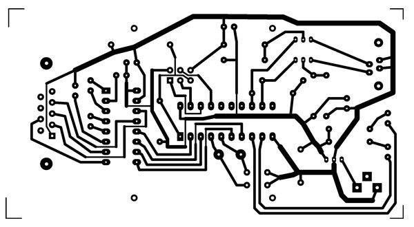
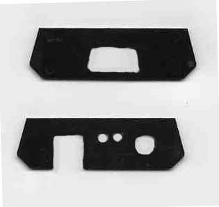
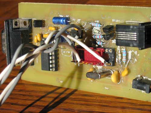
This single layer circuit board can  be easily made at home using instructions provided at the site (http://www.fullnet.com/u/tomg/gooteepc.htm) and the artwork above.   PCB size is 4.042 by 2.222 inches, so this art should be printed at exactly that size.

A couple of additional suggestions regarding fabrication follow.
  1. Use 320 grit paper to prepare the copper surface prior to ironing on the resist.  A scotch brite pad doesn't provide enough bite for the ink to stick.   Same is true for the silkscreen layer.
  2. To get all of the paper residue off off the silk screen side, soak the board overnight in water.  Then scrub with a toothbrush.
  3. Use of a drill press will vastly simplify and speed drilling all the holes required.   For the most part a size 64 drill bit will work for most of the holes, though a 68 would be preferable for the transistors (3904) and the voltage regulator (7805) parts.  I found a pin vice can be used to hold these small bits in a normal sized drill press.  Small drill bits can be found at hobby shops catering to model railroaders.
silk screen
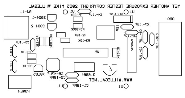
This artwork can be applied to the top side via making a laser printer decal or though ironing it on from laser printed photo paper.  Also note that this silk-screen artwork must be printed reversed so that when it is applied to the top side of the PCB, it comes out correctly.

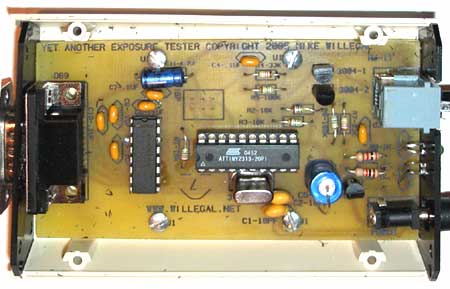
To assist interested enthusiasts in building their own Universal Exposure Timer and Event Counter:

End Panels

Here is the plan for cutting the end panels for the enclosure.  I used a dremel tool to cut mine.

end panels


Sensor Designs

Once built, this counter timer/device is easily adapted to a wide variety of applications, simply by construction of a new sensor.  Although designed to be used with photo-transistors, this device can also use relays, transistors and many other kinds of electrical switches as a sensor.
stereo realist sensor
One unusual application I have come up with, is the simple Stereo Realist tester shown here.  This easy to build sensor the tests both lenses of a stereo camera at one time.  Other concepts might include testers for medium or large format cameras.  See the application section at the end of this page for a description of a Cub Scout pine wood derby car tester.

shutter tester module  

I also designed a high performance 35mm focal plane sensor.  This design has a real world response time of of 20 micro-seconds or less.  The etched faceplace design is easy to construct, but provides highly accurate placement of the sensor slots.  Note that I left most of the copper and wood unpainted in this picture for better visiblity on this page.  However both copper and wood surfaces facing the camera back are normally painted flat black in order to reduce reflected light.

 To build a sensor for this 35mm focal plane shutter tester, you need to collect and construct a few components.
RJ connector
My plan is to release several JAVA applications including source code with free GNU license. Currently only the shutter tester application is available for download.
screen shot

The first application is the Shutter Tester application.  It will:
See the notes for running this application here.

Download the currently released Java source for my shutter test app and the precompiled application for Macintosh OS X.  You need to build and install the rxtx-2.0-7pre1 run time library in order to access the serial port on the Macintosh.  Keyspan sells a USB to serial dongle that works well on the Macintosh that has no built in serial ports.  The JAVA source code should be easily portable to other platforms. The shutter test app for Windows 2000.
Platform Independant Info.

Speedometer

This application's uses are limited only by your imagination.  Ideas include:
 
speedometer app

You enter the distance between sensors (using inches for English or mm for metric).  Then just enable the software to monitor the tester,  toggle the sensor a couple of times so it gets into the normally on mode.   Then watch the speeds cycle through the displays on the screen.  The selected display is the NEXT one that will receive incoming data.   You can enter a scale factor, to get scale speed, if you are dealing with a scale model.

Note that saving data to file is not tested or supported in current version.

Download Speedometer Application for Macintosh
 
Windows comming soon.

pinewood derby speedometer

Here is an example pinewood derby test track setup.  Two sensors are set at the end of the run and used to determine the speed of the car as it finishes it's run.  This picture shows the two sensors at the end of the track, with the car blocking the light to the second sensor.  When the car finishes passing over the second sensor, the counter/timer device will relay the speed information to the host computer.  Software on the host computer can determine relative or actual speed of the various test runs that are made.  Speed in miles per hour can be determined with the following formula.

d = distance between sensors in millimeters.
tm = time in milliseconds (second sensor start time *13)/36864
miles per hour = (d/1609344)/(tm/3600000)

I found I could use the existing shutter tester application to get relative speeds, but a dedicated application would be preferable.

Lap Counter

ttl to rs232 converter

TTL to RS232 Level Converter

Recently I discovered that my Sony Trinitron Monitor had grown over the years to be excessively bright.  In fact, with the brightness set to 0, it was still too bright and the picture was washed out.  After a bit of browsing on the web, I discovered that this was a common problem.  Since brightness was controlled by an on board processor, you could adjust the brightness back to "normal" levels, if you could get Sony's DAS software up on a PC and connected to the monitor.  The only thing I needed to do was to come up with a TTL to RS232 level converter.  This is because the interface on the monitor was a 4 pin header with +5V, GND, RX and TX at TTL levels.  After thinking about it for a while, I remembered that my universal timer/counter had the level converter and a DB-9 connector on board.  All I needed to do was remove the AVR processor and connect the wires appropriately to the socket and I had my converter.  I did this and it worked out perfectly.  Well I have a minor concern about whether there is any potential damage to the 5 volt regulator or electrolytic caps on the timer/counter by sourcing the power from the AVR socket.   Just in case I used a prototype timer/counter.  No apparent damage, but I will not be sure about it, until the next time I try to use this board as a timer or counter.  If you want to try this, connect +5v to pin 20, gnd to pin 10,  RX to pin 2 and TX to pin 3.

Other Ideas


Previous Shutter Tester Designs that I have Experimented With

  • Original Sound Port Shutter Tester
  • Apple II Based Shutter Tester


  • Back to Mike's Hobby Home Page