Model Railroad Automation Hardware
This page documents how I automated locomotive operation my City Point Terminal model railroad.
Go to this page to see how I automated switch operation.
Overview
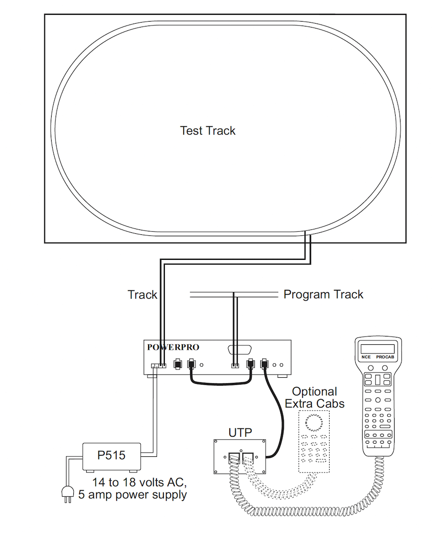
Basic Powerhouse Pro Block Diagram (from the manual)
The basic enabling technology for locomotive automation on my City Point
Terminal model railroad, is a NCE PowerHouse PRO DCC system. In a
DCC system, the control messages for the locomotive are generated by a
computer which is called the command station and the power that a
locomotive requires to turn it's motor comes from a special power
amplifier which is called a power booster. A combined power and
command signal is sent to the track from which
the locomotive both gets it's instructions and powers it's
motors. In a 5 Amp PowerHouse-PRO system, the booster and the
command station are combined into a single box, which is labelled
POWERPRO in the above diagram. Like many commercial DCC
systems, the command station uses a wired bus called a cab bus to
connect handheld throttles from which one or more users can send
messages to the command station, which in turn relays those commands to
one or more locomotives out on the track.
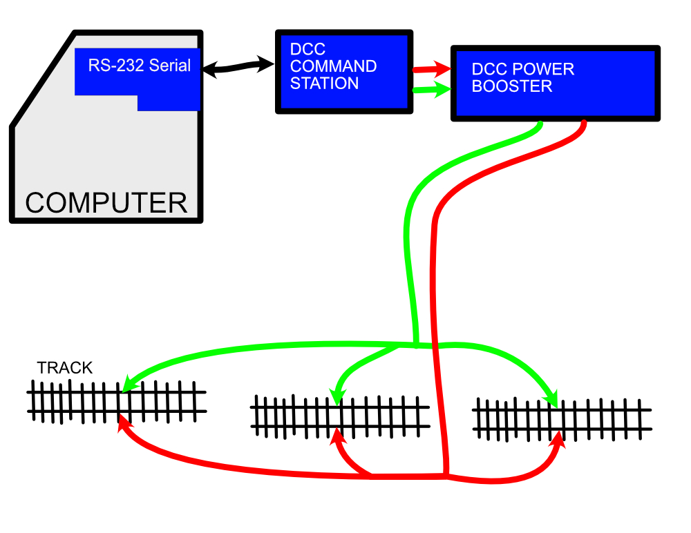
Basic RS-232 Communications
In addition to the cab bus, the NCE command station also supports input
from a RS-232 serial interface using a proprietary serial protocol that
is described in NCE documentation. This serial interface can
easily be connected to a computer which can be programmed to control
locomotives by sending messages to the DCC command station.
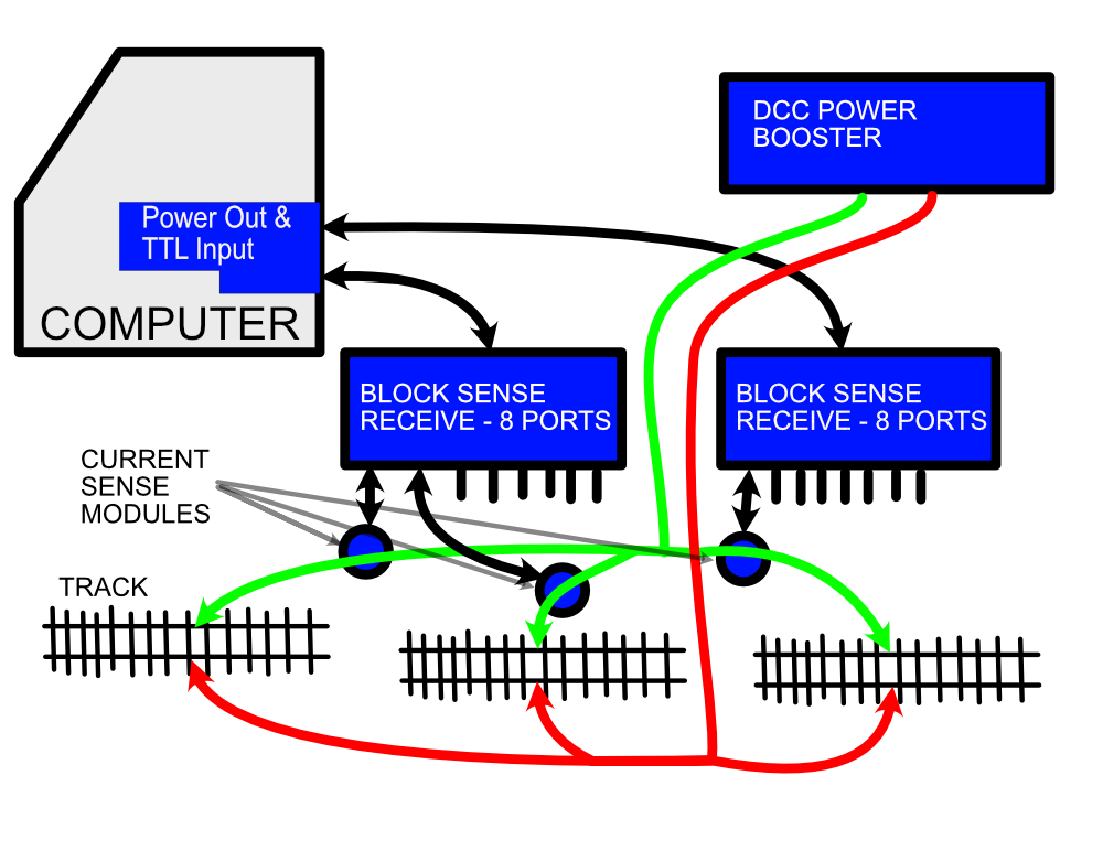
Basic Block Sensing With Three Blocks
In addition to being able to control locomotives, an automation system
needs to sense when a locomotive reaches a location on the layout, so it
can take action. For example, if the desire is to have a
locomotive stop when it reaches the end of the line or a station, the
automation system must be able to sense when the locomotive reaches that
point. The computer that is acting as the automation controller
will need to have sensor inputs in order to read the state of any
implemented sensors. There are many kinds of sensors that can be
used, each with it's own advantages and disadvantages.
Infrared detectors can sense when a train blocks a beam of infrared
light. This can be useful when it is important to have a sensor at
a very specific location. The disadvantage is that infrared
detectors must be mounted on the top of the layout where it can actually
sense changes in light due to a passing train.
Block sensors can detect when a a locomotive or specially equipped car
reaches a specific section of track. Block detection is usually
done by sensing when current is drawn from the DCC power booster by the
locomotive or a specially equipped car when it is in a specific section
of track. Track must be split into segments called blocks in order
to for this to be useful. Block sensors can only sense when a
locomotive or specially modified car is in a section of track.
Thus, the precision is limited to how long the section of track being
sensed is. One advantage is that the sensor can be be mounted out
of sight under the layout along with the DCC track wiring.
The design of my automation system is adaptable to a variety of types
sensor inputs, but at this point I have only implemented block sensor
input.
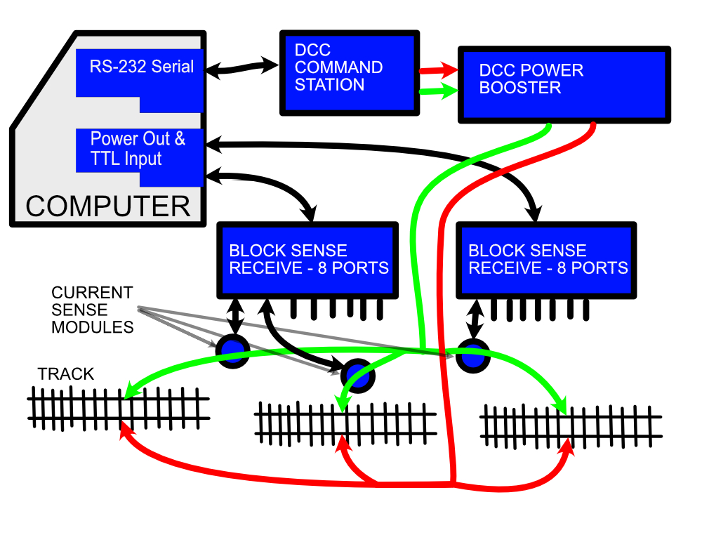
Basic Automation System With Three Sense Blocks
Combining the locomotive control system of the DCC command station with
an automation systems ability to sense locomotive location is all that
is necessary to implement a model railroad automation system. The
computer communicates with the DCC command station using RS-232 serial
signaling and gets status from the track through the sense system.
The rest of this document will delve into the details of the sense
system that I developed.
Automation Computer's Power and TTL Input Circuit
I choose to use an old Apple ][e computer as a host for my model
railroad automation system. One of the main reasons for this
choice was the ease in which I could add sensor inputs and control
outputs. Changing to a different host would involve replacing
the following interface with a circuit that is suitable for the system
to which you wish to port the application.
An Apple IIe has an integrated power supply, the BASIC programming
language, keyboard input and video output, and supports up to 7
expansion cards which are placed in card edge connector slots on the
motherboard. In my automation setup, one of the slots is used
for serial communications with the DCC command station. Another
slot is used for a floppy disk controller which makes saving and
altering the BASIC programs used to automate the layout rather
simple. This leaves 5 slots available for automation input and
output.
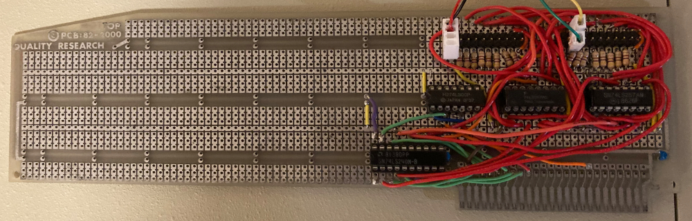
Prototype Sensor Input Board With a Single Test Input Connected
In order to get a basic automation system working, I decided to start by
implementing a card for reading block sense status. The card I
developed provides power and can gather status for up to 16 block
sensors. The input to the card comes through two 20 pin ribbon
cables. Each ribbon cable supports the power output, ground and
signal input for up to 8 sensors. A passive distribution
board to be described in the next section, is used to combine the
signals coming from the individual sensors to each incoming ribbon cable.
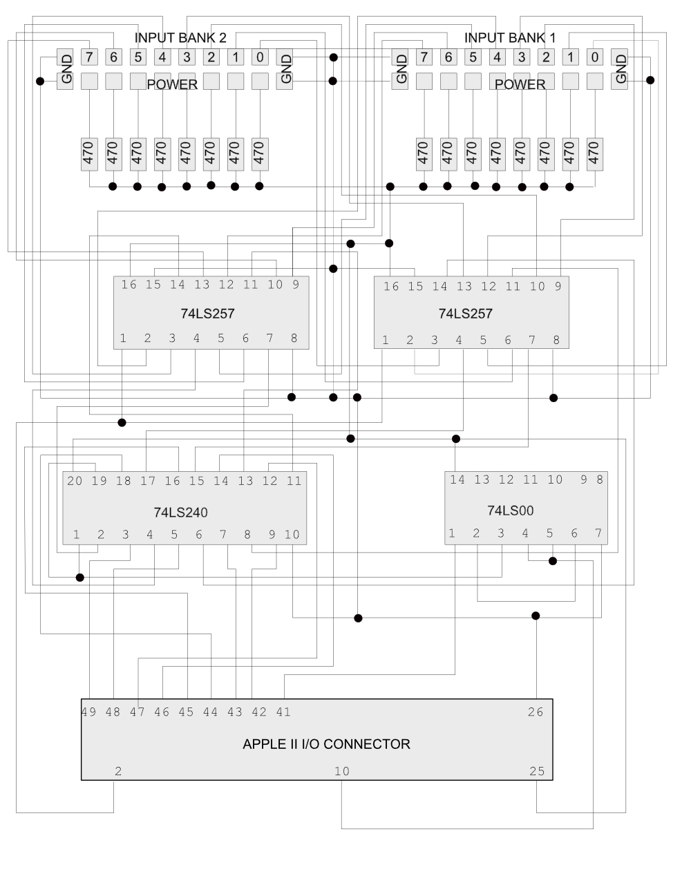
Sensor Input Board Schematic
The 74LS257 2:1 multiplexer chips steer either 8 bit set of sensor
inputs to the 74LS240 bus driver chip depending upon the state of Apple
bus address bit 0. The 74LS240 drives the Apple II data bus when
the processor reads from the slot in which this board is inserted in
to. That is the extent of the design for this card.
I could have added more banks of sensor inputs by switching to 4:1
multiplexers, but decided that it would be wise to limit the amount of
power consumption per card. In any case, there are plenty of
available slots, if I need to add more inputs in the future.
Sense Input Aggregation System
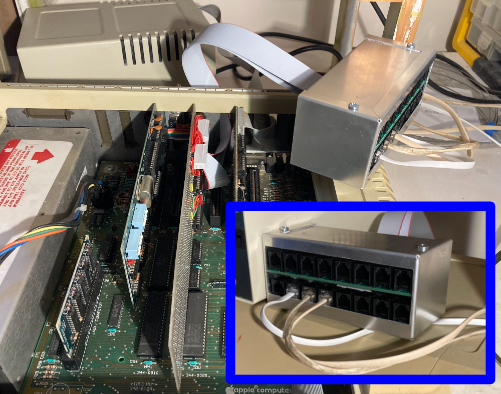
This Little Chassis Aggregates Sense Input
This box simplifies connection of sense inputs, sense power out and
ground. Each board takes the signals off two 20 pin ribbon cable s
and distributes to 16 RJ-11 jacks. All the grounds are tied
together and share the four ground wires on each ribbon cable.
Though only one board is currently installed, the pictured chassis can support
up to two aggregation boards for a total of 16 sense inputs.
Plain telephone cable is used to connect the signals from the
aggregation board to each sense circuit.
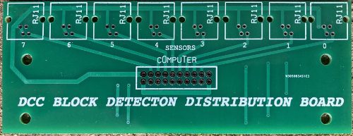
Unpopulated Aggregation Board
Block Current Sense Circuit
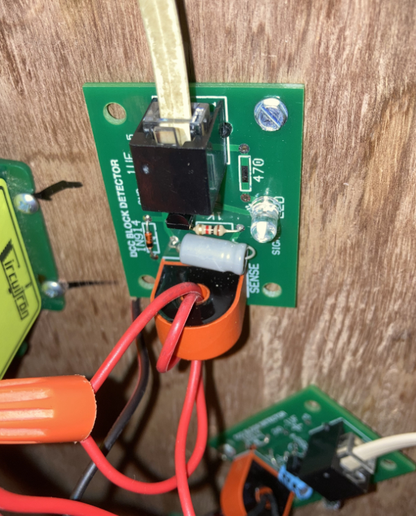
Installed Current Sense Detector
A key component of the automation system is a DCC current sense detector design that I found on the website: http://trainelectronics.com/DCC_Arduino/Current_Sense/index.htm
I first built a prototype of this circuit on a breadboard in order to
prove that it worked as described by Dave on his website.
In order to get it working reliably I found it best to use a much higher
value capacitor than Dave specified. After testing a number of
values I ended up settling on a 10uF capacitor.
I used a 1N914 diode and a 2n2904 transistor on my boards because that
is what I had in my stash, but I don't think that makes much
difference. I initially tested the circuit with a ferrite core
that I had laying around in a scrap box which worked fine. As I only had one of those I ended up buying the Gikfun
DIY 5A Range AC current transformer modules and made a batch of printed
circuit boards for the ferrite cores that came with the Gikfun kits.
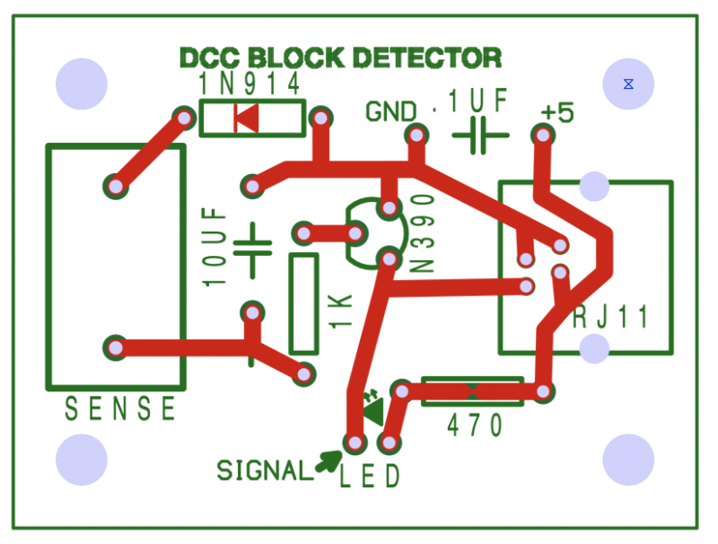
PCB layout - You Should Be Able to Easily Derive the Schematic From This Simple Layout
How This Current Sense Detector Works
One leg of the track power and the detector sense circuit are both wrapped
around the same ferrite core which makes the the core operate like a
transformer. When there is current flowing through the power wire
to the track, the transformer will transfer a little bit of the current
that is passing through to the current sense circuit.
The diode and capacitor act together as a rectifier and convert this
small copy of the DCC square wave signal into a DC level. When
enough current is passing through the ferrite core, the DC level will high enough that the
transistor will amplify it to the point that the TTL input on the host
computer interface board will recognize the signal as a high
input. This current flow also goes through the LED which
will light up. When little or no current is passing through the
ferrite core, the transistor will remain switched off. The TTL
input on the host computer interface board will read a low input from
the detector and the LED will have little to no current
flowing through it and will not be illuminated.
Connection to the aggregation box is via normal telephone cable with
RJ-11 connectors. Note that I designed my printed circuit boards
so the that the telephone connectors are oriented the same way on each
end of the cable which is different than some telephone
extension cables that I have purchased. I had to reverse the
orientation of the connectors on one end of those particular cables.
I made two other changes to Dave's design. I moved the 470 ohm
resister to the interface board on the Apple II computer. Just in
case I need to do things differently in the future, I designed the
circuit board with an option for a locally mounted resister. On my
layout, the resister location on the printed circuit board will be
left empty. I also put a spot for a power supply decoupling .1 uF
capacitor on the current sense circuit boards, but I found that I didn't
need to add that part either, so this spot on the circuit board is also
empty.
I found the circuit is very sensitive to number of times that the track
power line is looped through the ferrite core. The sense circuit will have some effect on the track voltage when a
locomotive is operating and drawing current. The more wraps, the
more sensitive the circuit will be. More wraps will also increase
drop of the track voltage, so there is a bit a compromise involved in
setting these current detectors up. For now, I have configured my
current sense detectors with two loops and pretty low sensitivity.
Of the three locomotives I'm experimenting with at the moment, only a
Bachmann Spectrum 2-8-0 with sound installed will trigger the current
sense when not actually moving. This is because only the DCC
decoder will be drawing current when the motor is not being used and DCC
decoders are pretty low current devices. My
software is able deal with this because it knows when locomotives are in
a block and are not moving. The software can ignore the sense input during these periods.