The Process of Creating the Apple 1 Mimeo
How Did I Do This Project?
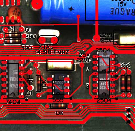
This
image will give you an idea of how I use the scan of an
original to make sure that component placement and traces are as
close
to the original as possible. The red overlay shows pad and
trace
placement as exported from my CAD program. The black is the
silk
screen layer, also exported from my CAD program.
Any discrepancies can easily be
seen
when this CAD output is placed in photoshop over the photo of an
actual
Apple 1 board. I expect most of the layout of the finished board
matches the original
placement within 10 mills. That is 1/100 of an
inch. There are some traces
that are routed under chips that are best guesses based on
experience.
Here is pre-production image
showing the PCB as seen in the CAD program. The final
production board has been tweaked and improved beyond what is
shown here.
- Black
is
silk screen
- Green is the front solder mask
- Red
is front copper layer
Check
out my blog for a
history of this project and continuing updates.
Check
out this
image of a pre-production version of the layout overlaid
over an actual
image of an Apple 1 (large file >1MB)
Note
that there is some distortion in the Apple 1 image, that may cause
less
than perfect alignment in some areas. This is particularly
evident in the upper left corner. The final production board
has been tweaked and improved beyond what is shown here.
- White
is
silk screen
- Red
is front copper layer
- Blue is solder mask over
fiberglass
- Purple is solder mask over copper layer
Follow this
link for some
info on parts and sources for the Apple 1
Results
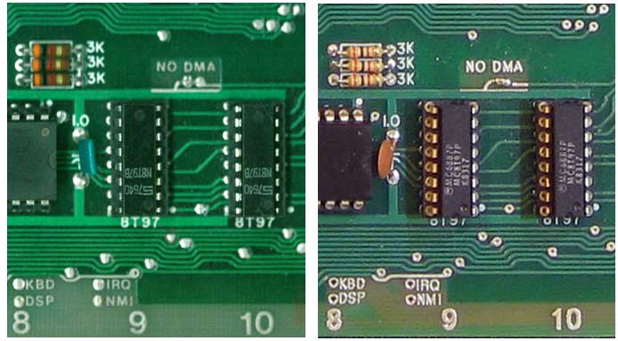
In
order to give you an example of the results, here are two larger
than life size
images - the image on the left is that of an original Apple1, the
image on
the right is a Mimeo 1.
One
of the things I'm most proud of, is the attention to detail I put
into
the solder mask layer. Note how the mask exposes some of the
trace above "IRQ", but not above "KBD". However there is just
a
nick cut out of the trace to the left of "KBD". Just a
sliver of the trace below "NO DMA" is also exposed.
I had to give the PCB manufacturer special instructions not to
"fix" these areas.
I
am also very satisfied how the lettering came out.
Recreating
the font and placing the letters was very time consuming. In
many
cases, I had
to individually place letters in order to get spacing between them
to
look the same as the original. The lettering that was etched
in
copper looks a
little heavy in these magnified web images. However they
look
fine when viewing an actual PCB. I have frozen the artwork,
and
I'm not likely to change anything in future production
runs.. In
my
experience, any improvement in one area can be offset by an
unintended
regression in an other.
Kit
Builder Feedback
I
received this feedback from the owner of an original Apple 1 and an
Obtronix Apple 1 clone. He bought a Mimeo kit as a learning
tool
for his teenage son, who was interested in computers.
- "I
have checked your Apple 1 board. It looks perfect. You did
excellent
job reproducing the original design. I am really looking forward
for my
son putting it all together."
Here more feedback from a person that at one time had several
original Apple 1s in his possession.
- "Wow! The board looks incredible. What an
impressive piece of work you've done. And the PC fab
facility as well."
more feedback from other folks
- "The kit arrived the other day, thank you! I had a quick
look at the board and it is beautiful!" - RL
- "Just
wanted let you know I got your kit! I have only opened it so far
and
looked at the manual and components. I am impressed with the
workmanship. Nice job! -RD
- "Everything is fine and it
worked on the first run without any problems." ... "Thank you
very much
for you perfect work! The board is really beautiful and some
older
parts as well." - ML
A few Mimeo owner's web pages and blog entries