
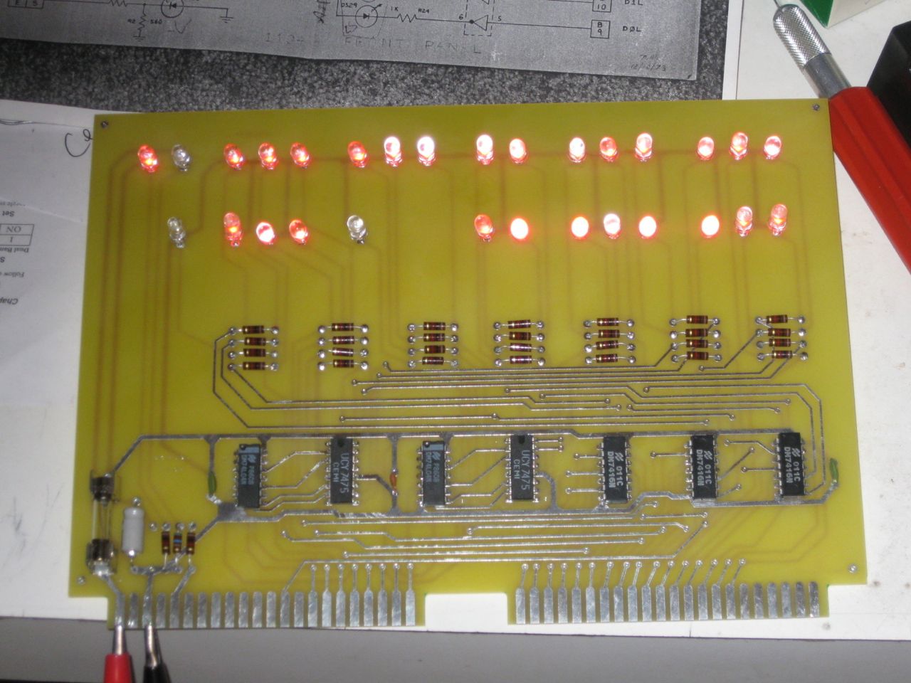
It looks real pretty lit up like this. I still need to straighten out the LEDs and cut off the leads from the back side. I simply connected a +5 volt supply to +5 and ground connections on the edge connector.
The three lights that are not on are -9 volts, run and stop. Run and stop are not driven by on board drivers. The other lights are driven by on board buffers. The inputs float high, so the LEDs come on, even with nothing attached.
In this configuration, the board is drawing about 220 milliamps.
The 6.3 volt zener which is used for overvoltage protection, is not installed.
Based on the description in the assembly guide and the early flyer picture, the LEDs originally used in the very first units were mounted in metal case. Here is a link to an image of this type of LED.
http://www.wired.com/gadgetlab/2012/10/the-history-of-led/
And here is a link to the flyer with a SCELBI with this type of LED.
http://www.scelbi.com/files/docs/advertisements/Flyer.pdf
Later SCELBI’s had the same type of T1 3/4 package that we commonly see today. They are red in color and have clear lenses. All the surviving SCELBIs that we know about use this common LED. The LEDs I’m using are part number L05RWC from led-switch.com and seem like a good match for the originals.
The fuse holders are Littelfuse 102074 which can be found at onlinecomponents.com and elsewhere.
Mike, Awesome. Great work as per usual! When will these be ready for public consumption? 😀
JC