Prototype Chassis with backplane installed – top view
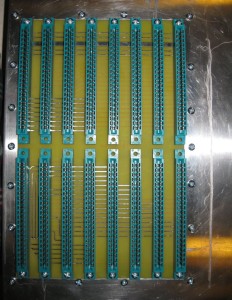
SCELBI chassis-top view
This is the result of some hacking of a backplane into a BUD AC413 chassis. The AC413 is the same width (12″) and depth (10″) as an original SCELBI chassis. However the BUD AC413 is 3 inches tall, while the original SCELBI chassis 3.5″ tall. During this prototyping/hacking effort, I found out a few important things.
Cutting aluminum is not hard, but it’s best to drill holes with a jig or at minimum use a punch to mark the center of the holes in the aluminum. I eventually used one of the scrap backplanes from the first delivery to create a jig for drilling holes.
On a “real” SCELBI chassis, the cutout for the edge connectors fits very tightly around the perimeter of the edge connectors. Making the cutout any larger than necessary, makes it very difficult to locate the support screws on the sides of the backplane. The edge connectors extend 8 7/8″ left to right and 5 5/8″ front to back. The backplane is 9.5″ wide and if the hole is made 9″ wide, that leaves only 1/4″ overlap per side to drill a 9/64″ hole for the #6 mounting screw. If possible, it would be best to cut the hole for an exact 8 7/8″ side to side fit. Though it doesn’t look like it, my prototype left too much space between the edge connectors and the chassis, making fitting the side mount screws a challenge.
The cutout starts 1/2″ from the front of the chassis and is centered between the edges.
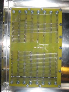
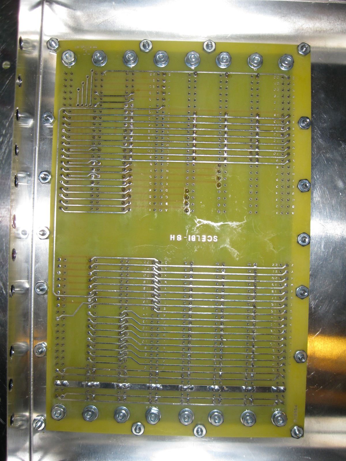
SCELBI Chassis Bottom View
A view from the bottom.
Screws holding the edge connectors/card guides have both a washer and star washer, but no lock tight on the original SCELBIs. I don’t have card guides and have used 1/2″ #6 machine screws.
Screws holding the backplane to the chassis have neither a washer or a star washer, but a held in place with red Locktight on original SCELBIs. I haven’t used Locktight, because I want to find shorter screws and I have more work to do on the chassis with the toggle switches and I/O connectors. The 3/8″ screws are a bit too long on my reproduction. A 1/4″ screw might be a better match to the original.
The screws at the front of the backplane do no go through holes in the backplane, but the edge of the nuts hold the backplane in place.
When soldering the edge connectors, only the pins with connections and pads are soldered.
One more thing – I positioned one of the holes for the edge connector mounting screws 1/16″ too far back. This hole will need to be drilled out to properly fit a #6 screw. However the error is so small that the enlarged hole cannot be seen under the nut of the screw or the ear of the connector.
An insulated stiffener running down the center of the board between the connectors would have been a good addition to this design.