
Nothing about the SCELBI is straight forward. The cutouts on the back of the chassis for the 78S type connectors is another example of this.
I puzzled over how to cleanly accomplish this for quite a few hours. Note that the power connector is a 86CP4 plug, so we are talking about 14 holes for the I/O ports and 1 hole for the power connector for a total of 15 holes.
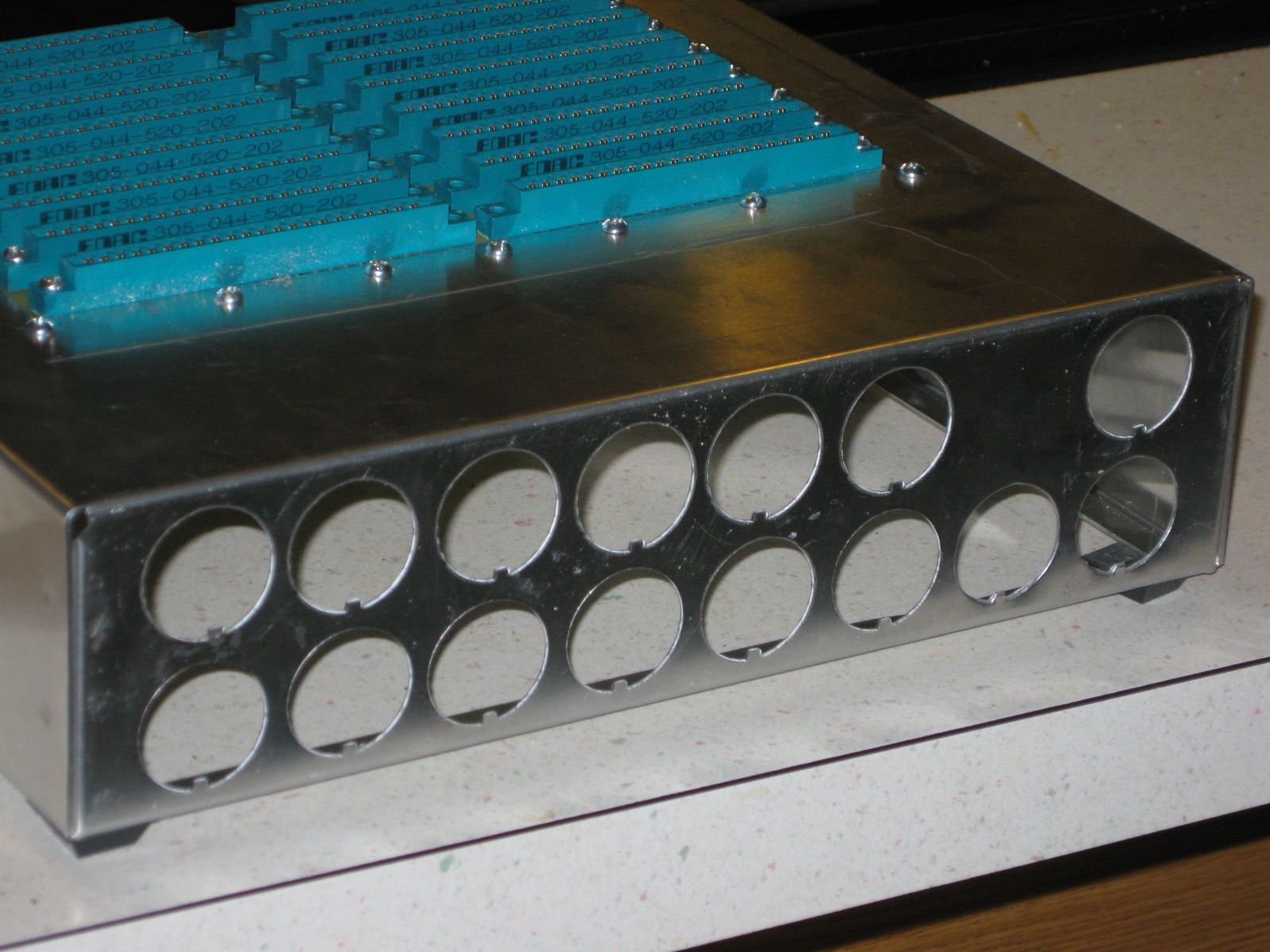
Back Chassis Cutouts
After much research, I finally happened upon a tool that was expressly designed to punch out these holes. The solution is a tool made by Greenlee called a radio chassis punch. The size you need for 78S type sockets is the type 732, sized 1 11/64″. They appear to sell pretty frequently for under $50 on ebay, but I happened to find a NOS one on a nearby distributers shelf for under $25.
Here are some example holes made by the punch. There is a 78S socket in one hole and the punch in another. You need to drill a 1/2 inch pilot hole before you can punch out the final hole with this tool.
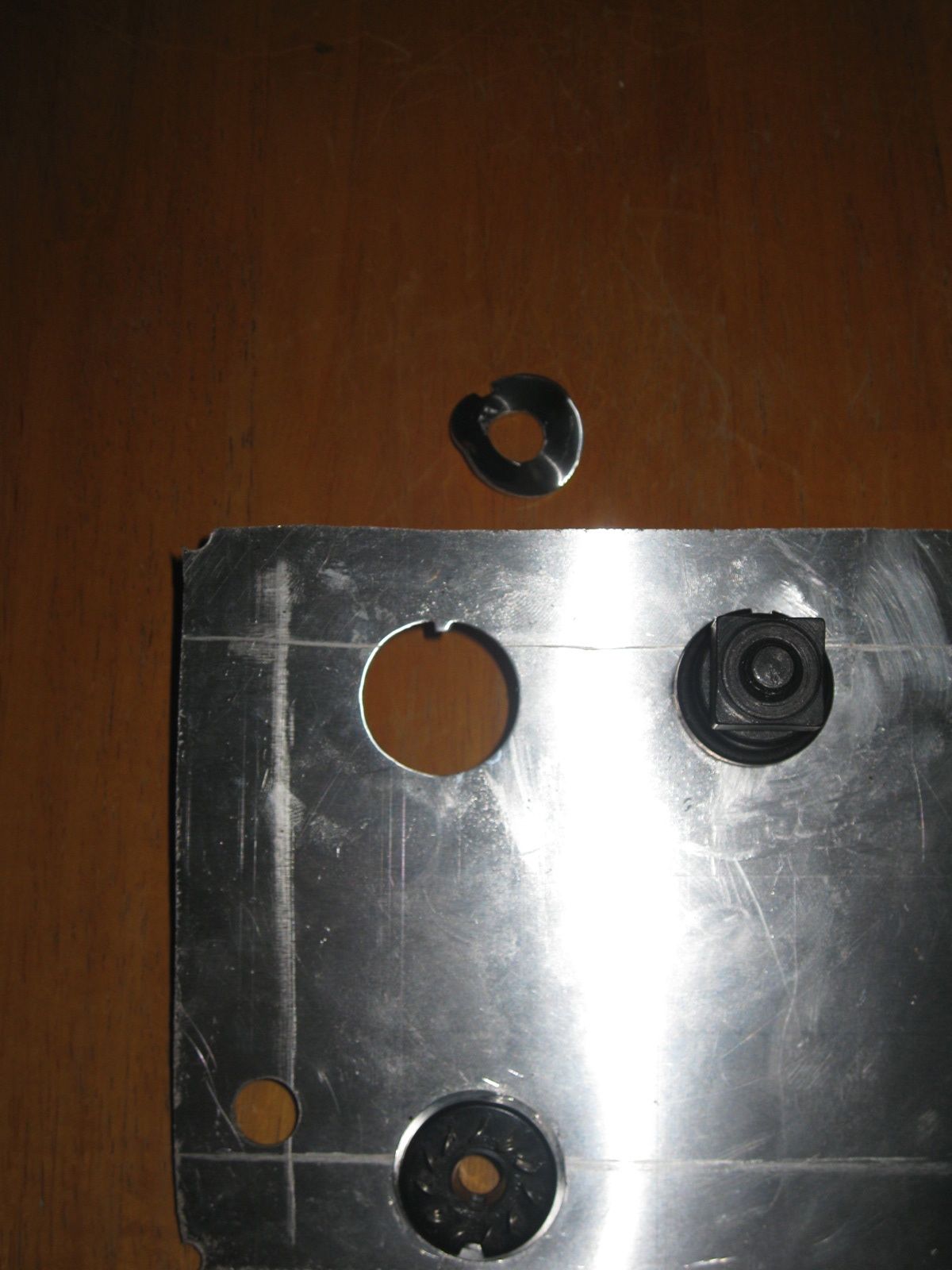
Trial Punch Holes
One thing I did to make punching out my chassis more accurate, was to create a pattern based on a 12″ by 3″ chassis back panel. I determined that the spacing between the 1 1/4″ diameter connectors is only 1/8″, so your layout has to be pretty accurate. My BUD AC413 chassis is only 3″ high, so you will have to adjust vertical dimensions a bit for a SCELBI 3.5″ high chassis.
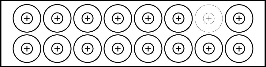
Back Chassis Pattern
The next step is to install all those sockets and wire them up.
This is awesome Mike, you are killing it!
Mike, did you need any band-aids or mild ER surgery afterwards?
No John, that chassis punch makes a real clean cutout, with no sharp edges.