
update 3/24/14 – I have corrected a mistake in the original posting – TX goes to pin 1, not pin 8 – sorry for an confusion that this might have caused
Take a look, it’s a lot cleaner than that bread board implementation that I showed in a previous post. The connections are simple.
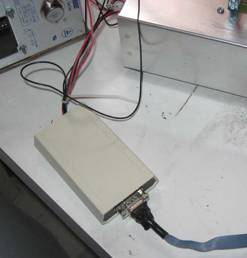
The enclosure is a Serpac A-20 that I had laying around. The PCB really only needs a 1.5 x 2.5 space to fit, but I had the A-20 enclosure and it makes a nice case for devices that need a DB-9 connector.
The PCB is single layer, with one jumper wire. This is about as easy as it gets when it comes to etching your own PCBs – single sided and pretty small.
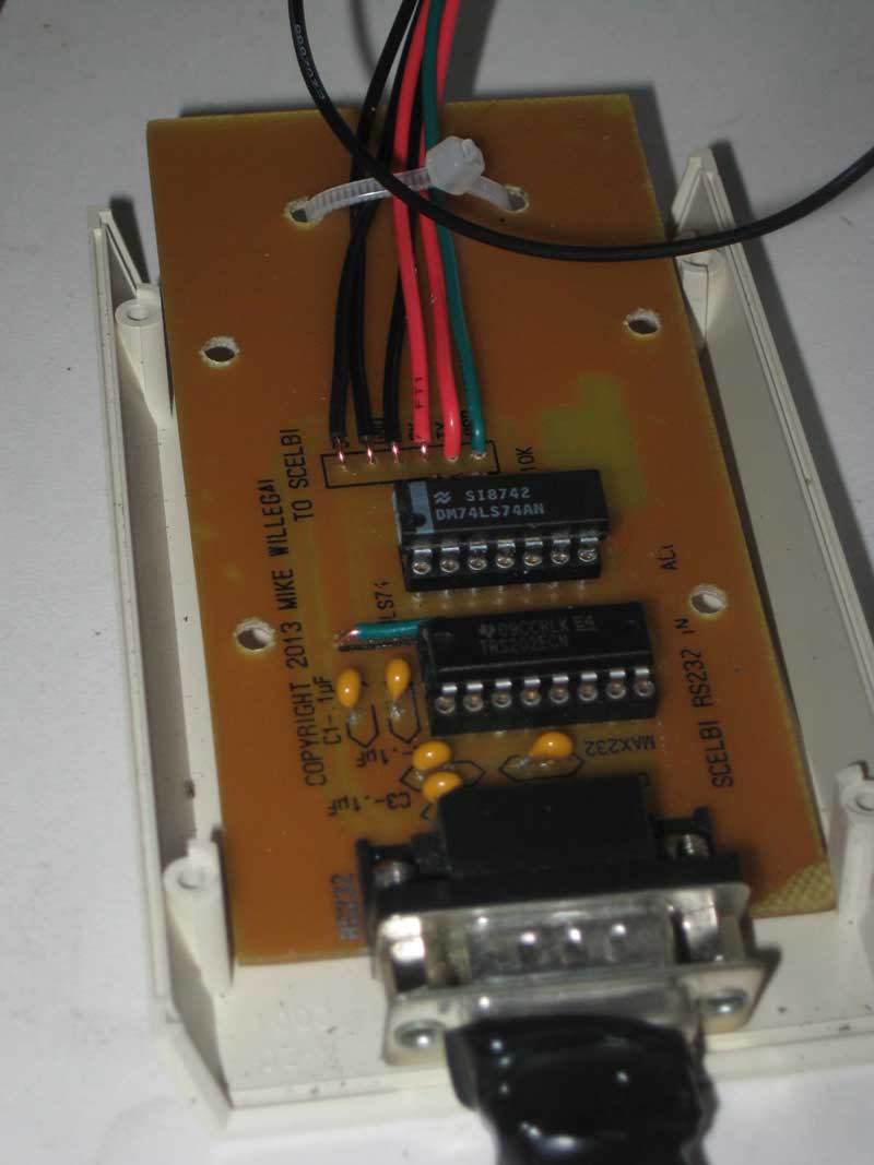
I etched it using the laser toner method, using glossy paper from a magazine (National Geographic) to make the transfer. The top side legend was done the same way. Put the legend on, after etching and before drilling for best results. I drilled the holes in a drill press with three different drill sizes – #67, 1/32″ and 1/8″. The parts list is pretty basic.
If you have a piece of scrap PCB laying around, like I did, the total cost of parts should be under $10, with over half of that being the enclosure. Actually I had all the parts on hand, and didn’t have to buy anything to build this interface up.
In the past, I remember marveling when reading magazine and web articles about people building nifty little gadgets with stuff out of their parts box. I would think, how could someone have enough in their stash to do that without buying anything. Well, I guess I’m somehow progressed to the point, where I’ve joined that club.
Postscript files that can be used to print your own PCB can be found here.
Where are the schematics? Well there aren’t any. With a single sided PCB, and only a few components, the art for the PCB is enough to use as the schematics. The RS232 interface side was lifted from a TTL to RS232 converter that I did a few years ago. That converter was largely taken from the RS232 portion of my PS/2 to parallel keyboard adapter.