
I just added the correct SCELBI power connector to my reproduction. Note that this was the factory setup. Back in the day, some people integrated power supplies right into the chassis, rather than using an external power supply. The plug is a 86CP4 and the socket is a 78S4. These days, they are kind of scarce. In this case, scarcity equates to price, as they are about 9 dollars each. Check inventory at alliedelec.com for 78S4 and at tedss.com for 86CP4.
Here are some images.
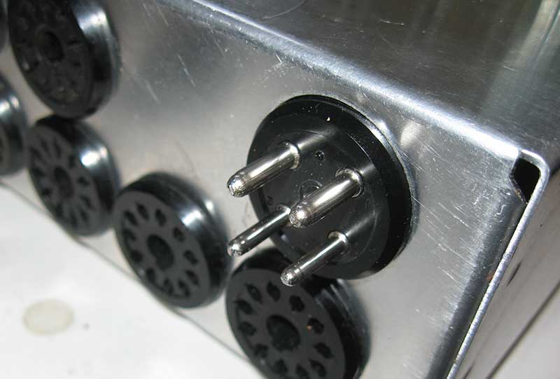
SCELBI Power External
You put the plug in the chassis so the cable coming from the power supply doesn’t have exposed pins.
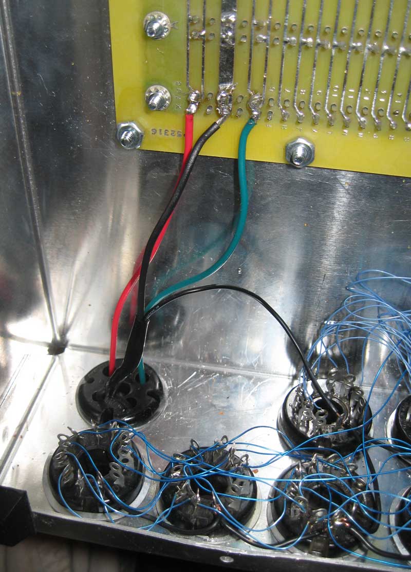
Inside Power Wiring
The SCELBI manual says put +5 on pin 1, ground on pins 2 & 3, and -9 on pin 4. SCELI assembly directions have you position 1 and 4 at the top of the chassis. This makes wiring to the backplane pretty clean. The slip rings that are used to hold these connectors onto the panel are a pain to get on – be patient and don’t expect the rings to seat perfectly. I chose to connect the I/O port grounds directly to the incoming ground wire, rather than wire back to the backplane. Now I’m thinking I should have run both ground wires to the backplane, rather than join them together and run 1 wire to the backplane. I used 18 gauge wire, so it probably doesn’t matter.
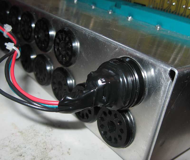
Plugged In
The socket and plugs are keyed, in that two of the pins (positions 1 and 4) are larger than the other two. However, I think if you weren’t paying attention, you could plug this in far enough to make contact and cause problems. Be careful when plugging this unit in.
I have used electrical tape to protect the exposed terminals on the cable coming from the power supply. I need to pick up some of the hoods that are designed to cover these connectors. SCLEBI used gray clad multi-conductor cabling back in the day. I think it is still available, but like many SCELBI components, it is pretty expensive.
This process took me a couple of hours. Take your time to get things right and avoid costly mistakes.
Next up – getting the TTY interface built up and checked out. Other than schematics, and parts placement, we don’t have documentation for that board, so it might take a while.