
The SCELBI uses an 11 pin Amphenol connector for output ports. The hardware manuals specify:
That leaves pin 10 as “open”. When I first built the SCELBI-8H reproduction, there was some speculation about possibly using 10 pin for +5 volts, instead of leaving it open. At the time, I thought this probably wasn’t a great idea, because of possible losses over the cables and connectors. However, the same concern really also applies to the ground wire, which is connected.
During research into the SCELBI peripherals, I discovered that the CPU SYNC signal is used on the Oscilliscope interface and the Cassette interface. We have some evidence that at least one SCELBI chassis had sync connected to some (or possibly all) output ports. Since only pin 10 is available, it makes sense to use it for SYNC for these I/O cards.
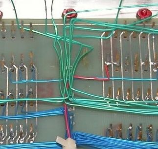
Sync is on Red Wire running from backplane to I/O ports
This is a crop of an image taken by Jack Rubin at the CHM a few years back. The red wire seems to be connected to the SYNC pin on the CPU card and runs back towards the I/O connectors.