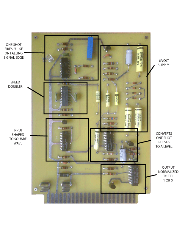
I’ve spent the last couple of days trying to get SCELBI cassette interface working. Though I have made tapes with the write card, I’m having trouble reading them back with the read card. I’ve also tried some original SCELBI audio files provided by Mark Arnold, but no go on those either.
Assuming that my understanding is correct, the read circuit works much differently than what I expected to find. As expected, the first op-amp shapes and filters the signal into a nice normalized square wave. The following gates double the input signal speed and trigger a one shot on each falling edge of this double speed square wave.
Now here is the interesting part. The output of the one shot is filtered and converted into a level by another op-amp. High frequency signals will trigger the one shot more often tending to make the input to this op-amp to average a higher level than with lower frequency input. The output of the op-amp will follow the input. A TTL gate will normalize this output into a TTL one or zero, based on normal TTL level detection on the gate input.
I was expecting this circuit to work like a tone detector, where the circuit only triggers on a narrow range of frequencies. Instead the circuit divides the input frequency range into half and outputs zero on the lower half and a one on the upper half. The demarkation point is pretty much right between the 1350 HZ used for low frequency (zeros) and 2700 HZ used for high frequency (ones). The potentiometer can be used to tweak the center point to some degree. Experiments show that the output appears to be pretty unstable in the middle frequency zone.
There is also a -6 volt power supply built into this card that is used to power the op-amps, so that the card only requires a single +5 volt supply.
The read program works a bit like a serial interface, by starting sampling on what amounts to be a start bit at the beginning of a burst of four bits. By my calculations, the first bit is sampled after about 2.2 milli-seconds and then a software timing loop samples the incoming signal for the remaining 3 bits at about a 1.5 milli-seconds interval. Each four bit data nibble, is paired with a 4 bit parity and state/status nibble that is encoded the same way. Two such pairs make up a complete byte.
The problem that I’m seeing is that the parity check fails all the time. So far, I can’t find anything obviously wrong, either with read or write, but I have a lot more things to check out before I become “stuck”.


What tape recorder / input signa do you use?
Sorry if I’m being captain obvious, but:
Any distortion will cause harmonics. Loud enough harmonics of the low frequency tone could trigger the detection of a high frequency tone.
I had commodore computers with their dedicated cassette recorder back in the old days when cassette tapes were the most common storage, but I remember reading that for computers that used a standard tape recorder the recommendation were to use a simple portable mono tape recorder and not a fancy hifi deck just because the simple tape recorders did less processing which actually gave better performance when used as a computer recorder.
If I were you I would probably find some way to test the software and the hardware separately. Since it’s TTL you could use some standard I/O port on a modern microcontroller (i.e. Arduino) or bit-bang a parallell port on a 80’s/90’s computer that is easier to program (i.e. Amiga, an old PC running DOS, C64 or similar). Of course a logic analyzer would probably be best…
I just figured it out – check out my next blog entry