
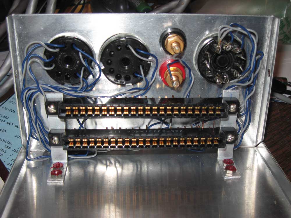
Many SCELBI ethusiasts have found the image of the Audio Cassette Interface in the Computer History Museum’s catalog page. I recently had a chance to check out an extremely rare original example and took the opportunity to take some pictures and measurements. Here is how the front of the chassis is set up. Wiring follows the schematic. Note that this picture is actually taken upside down, as the cards are mounted to the top half of the enclosure.
Inside Cassette Interface
Though the mechanical design is simple, building this chassis clearly involved a lot of manual labor. I wonder what would have happened if the SCELBI had started to take off like the Altair did. I think that Nat and Bob were very lucky to be able to move the company so successfully into publishing. The SCELBI Computer clearly would have required a complete redesign in order to compete with the coming wave of inexpensive, mass market, micro-computers.
From this upside down perspective, the read card is mounted facing up, in the upper slot, and the write card, in the lower slot. There are holes in the bottom of the enclosure for viewing the LED on the read board and a hole in the rear for adjusting the POT, also on the read board.
The binding posts for power and ground are very nice examples with heavy gold plating. Unfortunately, I couldn’t find any manufacturers markings on them.
What is not so good, is that the horizontally mounted cards are not supported by anything other than the edge connectors. This means that rough handling could easily cause damage or connectivity issues, particularly with the rather long cassette cards. Many systems, such as the wildly successful Apple II, used non-supported peripheral cards in edge connectors, but the cards are usually mounted vertically so that gravity will help hold the cards in the slots.
It’s not visible in this view, but the pins from the top and bottom rows of each edge connector are soldered together in each position where there is a wire connected to the edge connector. I’m not sure why this was done, as no signal lines were connected to the top side of the edge connectors on the cards. I also got to look at a TTY enclosure. That enclosure had a different type of connector with single row of pins installed.
When I get a chance, I’ll be posting more images and make up drawings with measurements.