
Thanks to Jack Rubin, I have two pictures of the inside of the only known SCELBI Oscilloscope Display interface. Here is one of them.
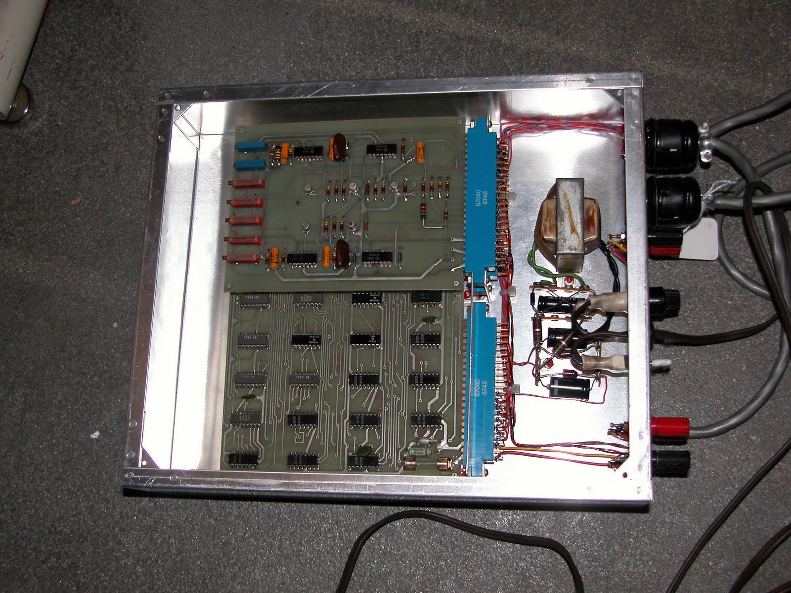
SCELBI Oscope Internal
To me, the surprise was the small power supply located in this chassis. Further research indicates that it was used to power the analog board, which contains 4 SN72741 op amps. The data sheet of these op-amps indicate that they take a +18/-18 volt split power supply. This also can be seen in the SCELBI schematics. Since I had only this and one other picture to go on, at first I wondered whether I could figure out how this supply was constructed. However, it didn’t take too long to come up with the following schematic.
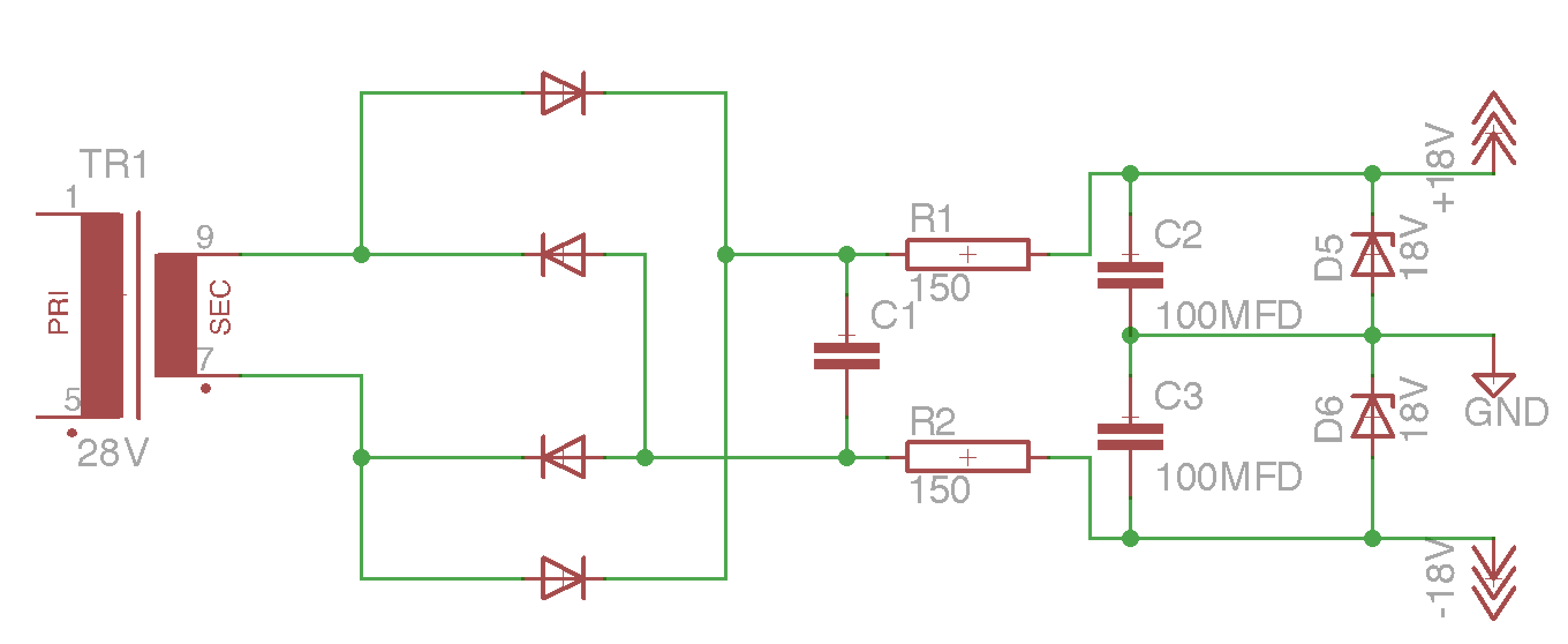
SCELBI Scope power supply
Ignore part numbers in this schematic. The resitors appear to be 150 ohms, probably 1/2 watt. The smoothing caps, C2 and C3 on the +18 and -18 supplies appear to be 100uFD, rated at 10 volts. 10 volts seems to be under rated for an 18 volt supply. I don’t know what value the first smoothing cap C1 is, but it should be rated for around 50 volts. I also don’t know exactly which rectifier diodes, D1-D4 are used. The zenor diodes, D5 and D6 should be 18 volt devices and are used to set the output voltage.
In order to confirm my schematic, I rigged up a test power supply, using some parts that I had on hand.
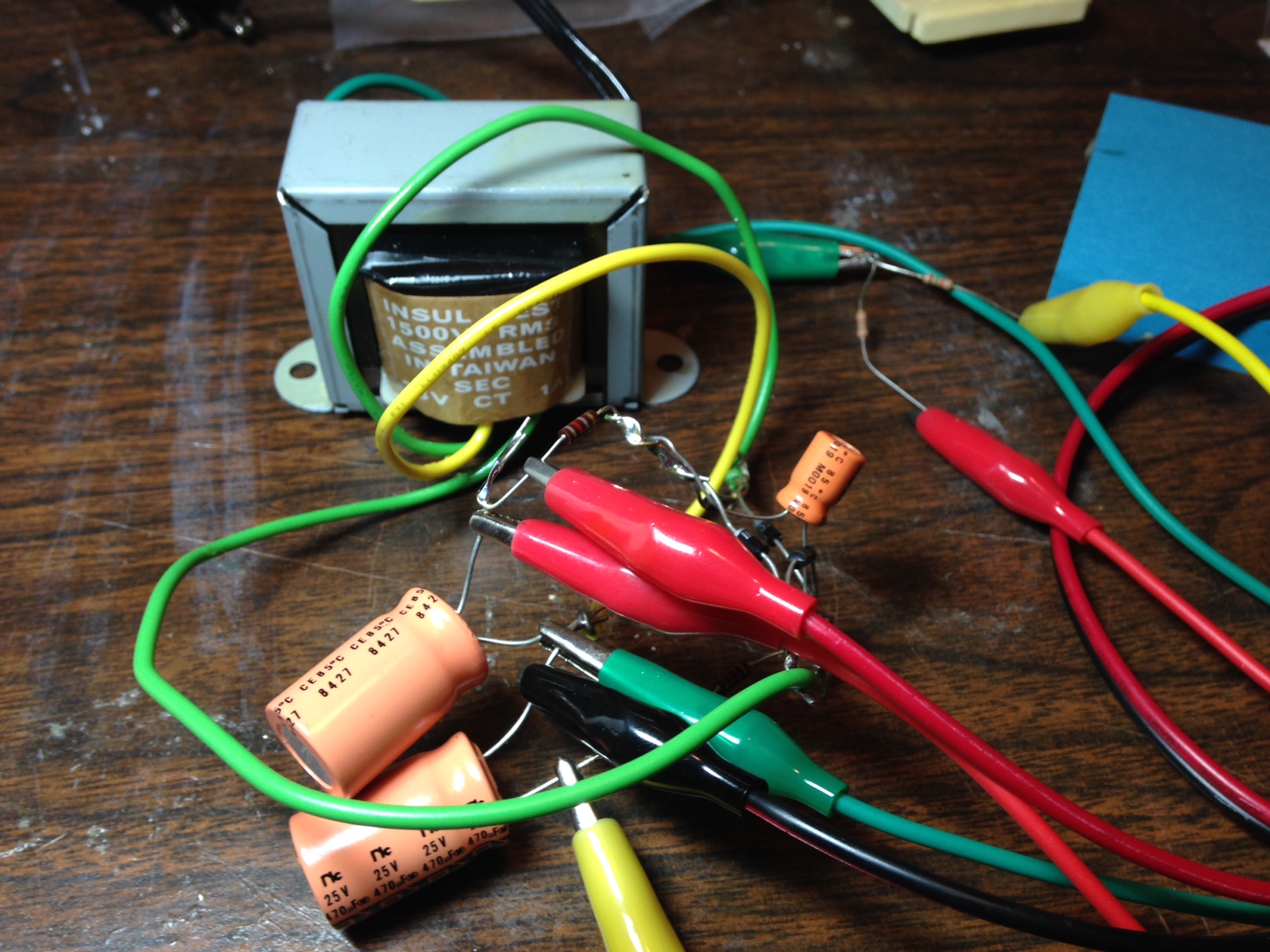
Scope Analog Supply Prototype
This test jig lacks the zenor diodes, and uses an 28 volt transformer. Output is around +/-20 volts, which should be about right. Next, I’ll have to find some 18 volt zeners and see if I can power the analog board with it.