
I finally took the time to figure out why the Oscope Y axis is upside down. It all stems from an error in the schematics.
Analog Schematic Error
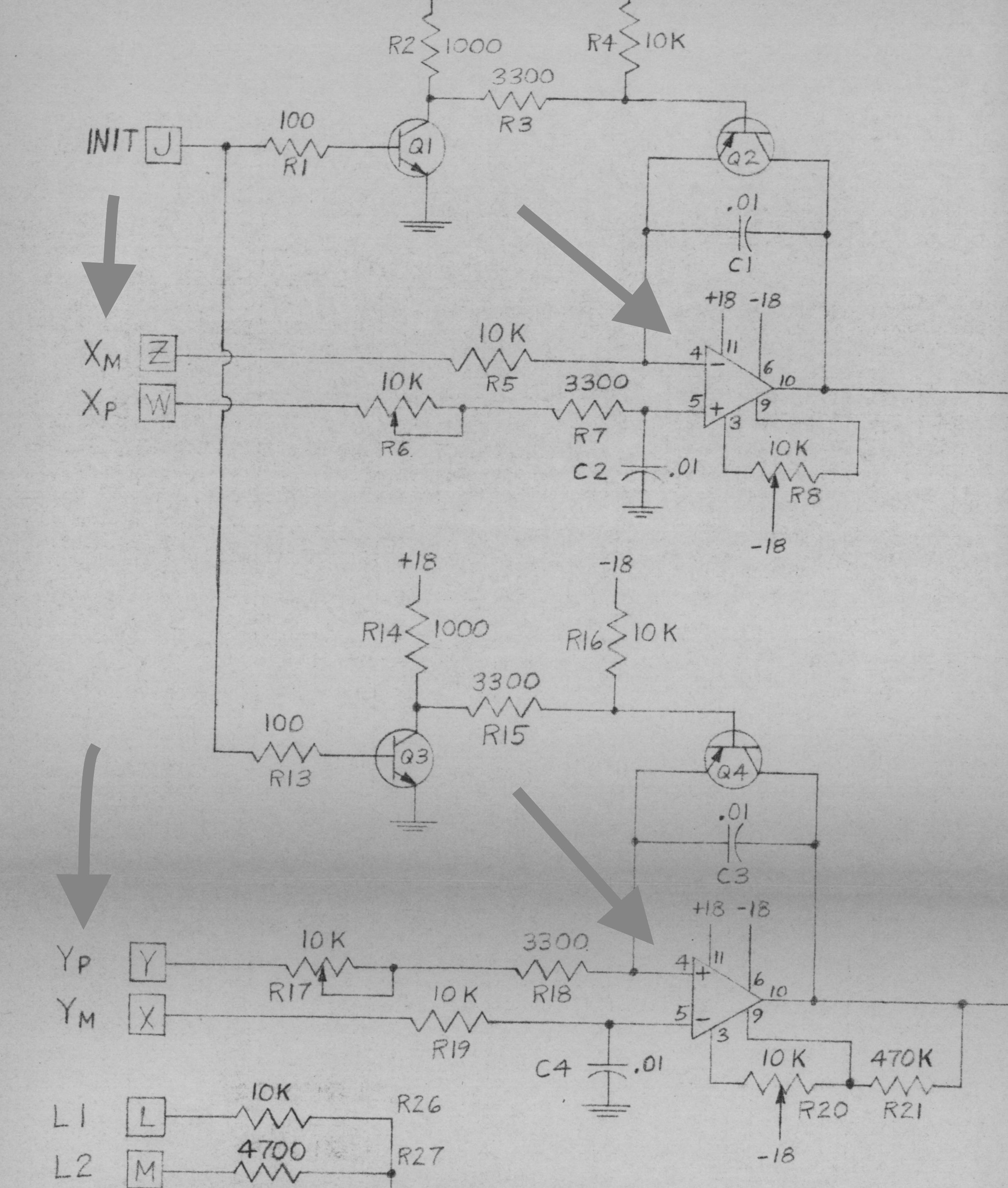
If you look closely at this cropped image of the schematic, you will notice that pin 4 of the Y axis op-amp is labelled (+) while pin 4 of the X axis op-amp is labelled (-). Both can’t be correct, as op-amps all have a negative and positive input. Here is the pinout of the SN72741 from the TI data sheet showing that the correct labelling of pin 4 should always be (-).
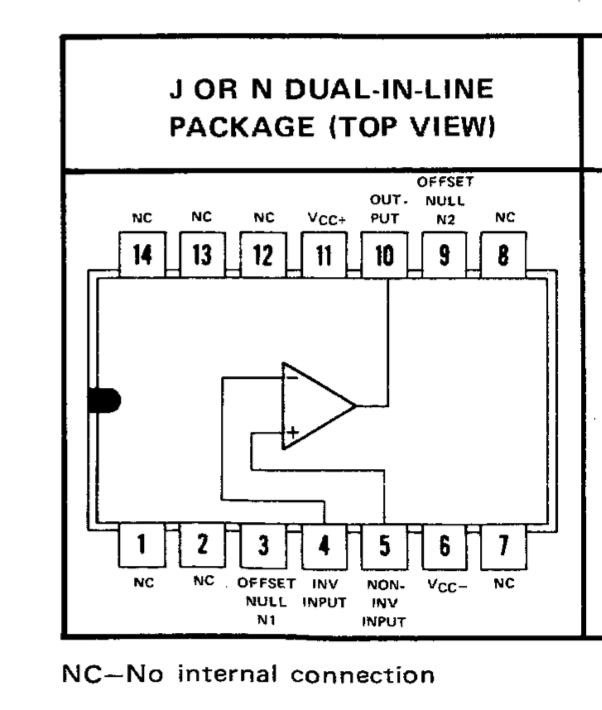
SN72741 Package
The X and Y, plus and minus inputs to the analog board come directly from the digital board. If you look look at the digital and analog board schematics, the X and Y outputs match up nicely with the analog board inputs.
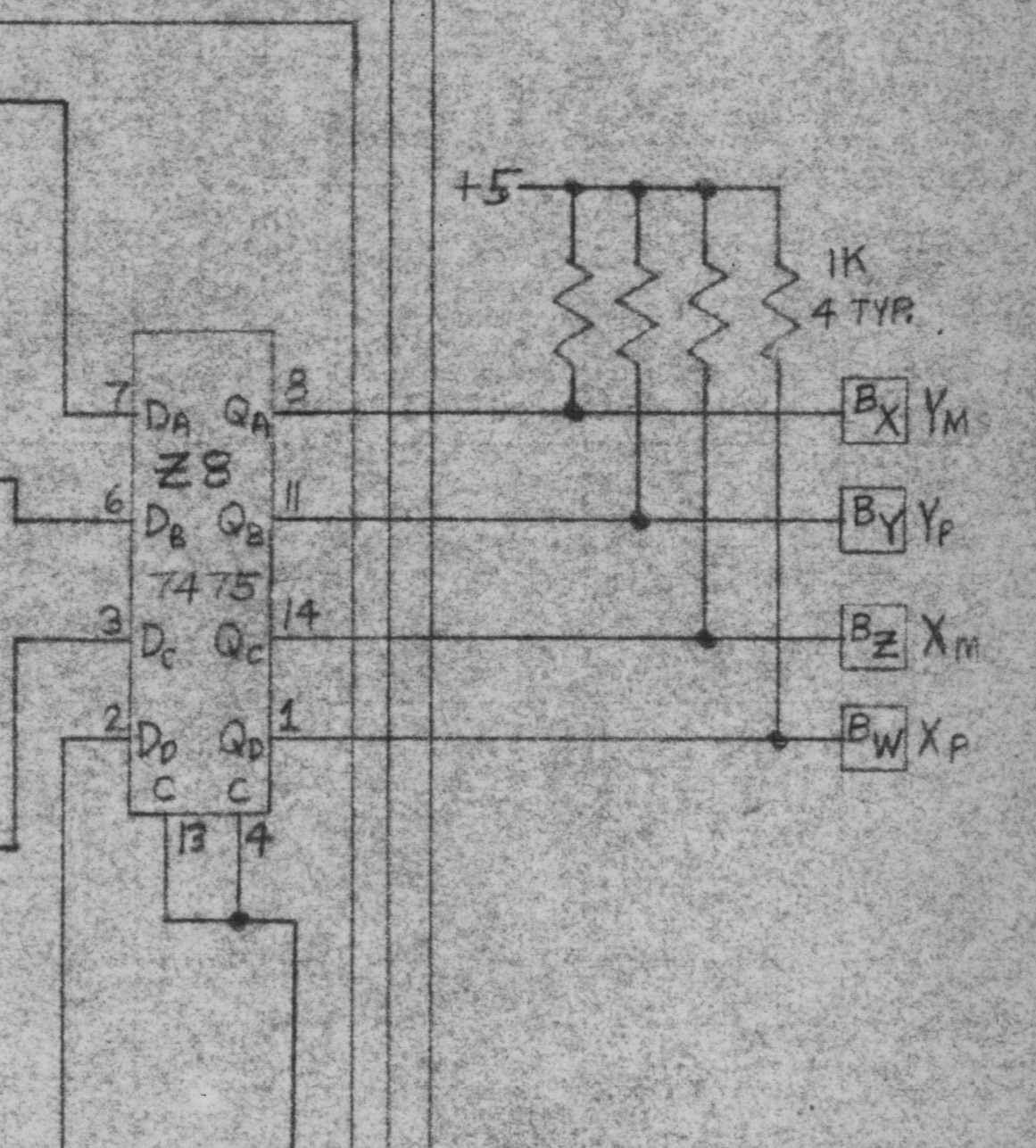
Digital Board X and Y Outputs
There is an image showing how I connected them in a previous blog post. Pins W, X, Y and Z are to the far right in the following image.
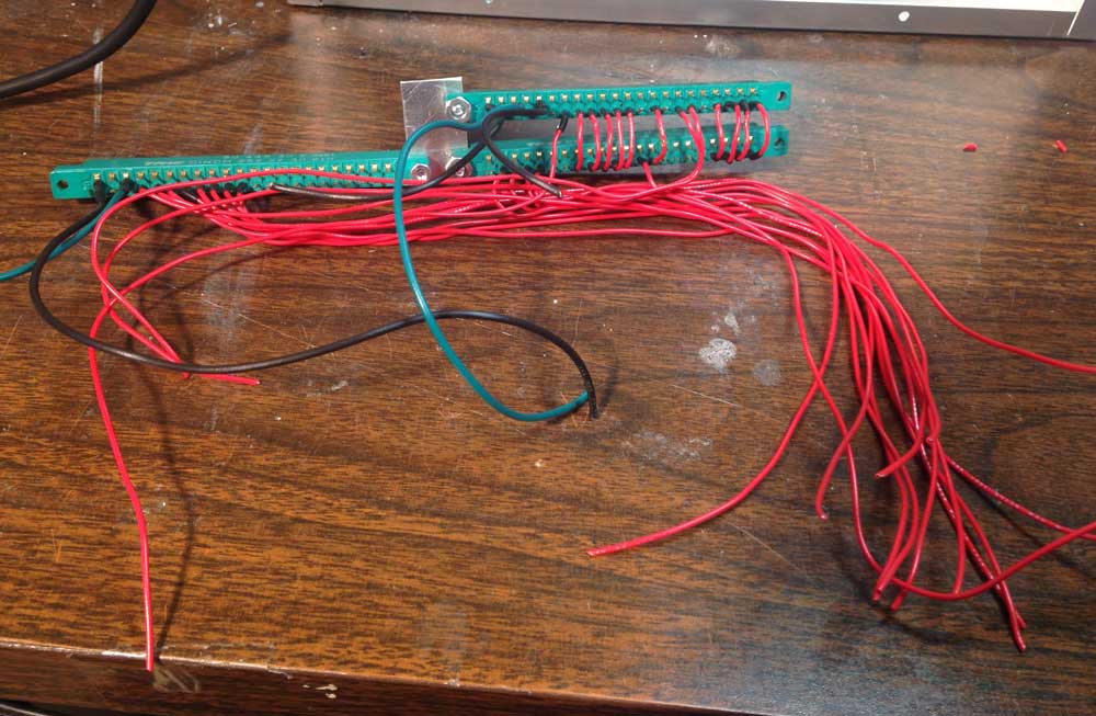
Edge Connectors Wired
Overall, it looks like a very clean solution. The problem is that the mislabelling of pin 4 and pin 5 of the Y axis op-amp caused the Y inputs to also be labelled backwards on the analog card schematic. Therefore, Y plus is really connected to Y minus and visa versa. The solution is to cross the connections for Y plus and minus between the digital and analog boards.
I would have to assume that this swapping was done when constructing the original SCELBI Oscilloscope Interfaces, but I don’t have access to an original unit to confirm. The images I have, don’t show the connections between boards, so I can’t go on that. I would also assume that the intention of the design was to make connecting the boards easy, and if enough units were built, that Y minus and Y plus would be swapped on the PCB, so that connecting the digital to analog board, would be more straight forward. My guess is that so few oscilloscope cards were made, that this change was never made.
Fortunately, I’m pretty sure that I will be able to swap these connections, without dissassembling the entire Oscilloscope Interface.
Nice catch – hope the swap is easy.