
In the following image of the Digital Group Video Card, the ground traces are highlighted in green.
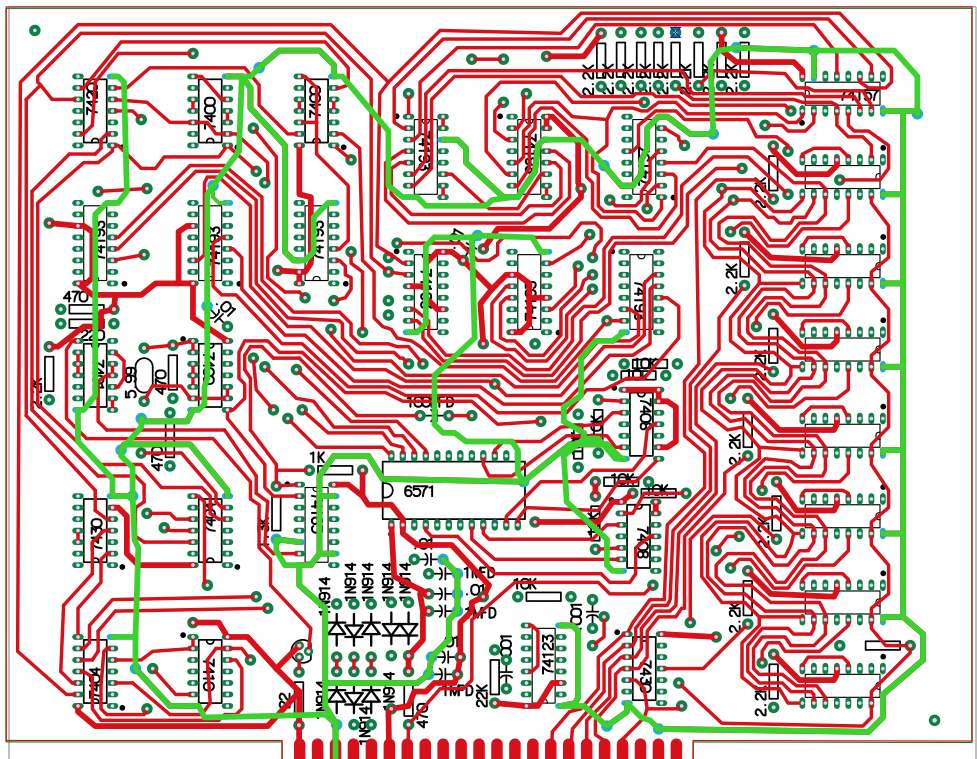
I normally I try to refrain for making severe criticisms of the boards I work to reproduce. The people who designed these products were blazing new trails, something that should be respected. However, the routing of ground traces on this board appears to be something that should avoided by people producing new designs. Note how the route to ground for the 74123 (in the bottom center) runs completely around the exterior of the board before exiting on the board edge connector, which it is almost touching. When I finally build one up, I wouldn’t be surprised if I have ground issues with this design. The good news is that it should be pretty easy to resolve any issues that do crop up.
I have quite a bit of fine tuning and clean up to do before ordering a PCB, but as you can see by viewing the layout image in this post, the hardest part of the work is done. The existing schematics don’t have any kind of chip ID or location, other than part type. I’ll be rectifying this and be publishing a parts list, chip placement diagram and updated schematics, by the time I’m done with this project.
I discovered one other issue that I’ll have to deal with. The 6571 character generator needs a +12 volt supply. For now, I can use a separate 12 volt lab supply. I think I’ll have to create some kind boost converter to generate +12 from the +5 volt supply by the time I’m done with this project.