
In a previous post, I have noted that the MCM6571 character generator on the DG video card requires a +12 volt power supply. +12 volts isn’t normally available in a SCELBI computer system. Now that the PCB layout of the DG video card is nearly finished, I took some time to look into building a circuit that could supply the +12 volts for the character generator.
Here are the basic requirements that I came up with for this supply.
According to the data sheet, the MCM6571 requires a 12 volt supply that will supply 8 milliamps of current, worst case.
In order to keep things simple, I think it is best to generate the 12 volts without the use of a transformer or use of mains power. That leaves the 5 volt supply as the source of power to a voltage boost circuit. This circuit would have to boost those 5 volts up to 12 volts. Not being a power supply expert, I hoped I could find a design on the internet that could do this for me.
It turns out that there are lots of modern, inexpensive solutions for generating 12 volts from a USB interface’s 5 volt power, but almost all of those, use modern linear ICs. In order to keep things vintage, I want to use components that were commonly available to hobbyist in the mid 1970s.
Continued searching of the internet revealed a few transistor based solutions. I looked for a design that might be made up from components that I already had in my stash. This would make building a prototype easier and avoid the expense of ordering or spending time looking for parts in the one store we have in my area that stocks electronic components. I picked out a likely design and then searched my stash for the needed components. I managed to find enough parts to put together the circuit on a bread board. Unfortunately, after spending several hours debugging it, I found that I couldn’t get this circuit to work.
I gave up and went back to the internet. A new search revealed a slightly simpler circuit that used many of the same components that I had used on the first circuit. I already had found most of the needed components while building the first prototype. I built this second, similar, circuit in almost no time. After replacing a bad diode, and correcting the orientation of the transistors, which I had inserted backwards, this circuit sprang to life. One thought I had, was that the bad diode probably was the source of the problem with the first circuit. I decided to not to revisit the first design and I pressed onward with this new circuit.
My prototype has a few slight changes in component values. The nearest value inductor I have on hand is rated at 390uH. I didn’t have a 6.8 ohm resister to use for R2, so instead I used a 10 ohm resistor. I used 2n2222 transistors instead of the BC337 specified on the schematic. I used a 1N914 diode instead of the 1N4148, as my understanding is that these are equivalent parts. One other difference is that the zener I had in my stash is rated at 12 volts, not 13.
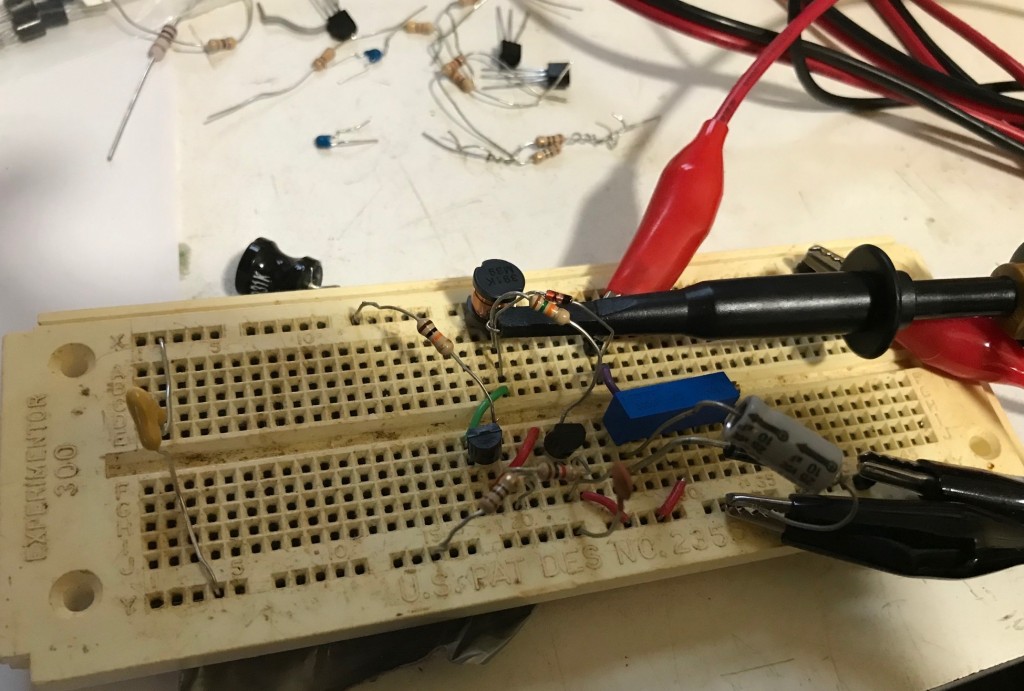
There are decoupling and smoothing capacitors on my prototype, as shown in the schematic. However, depending upon how I connect it to the DG video board, I may just rely on the DG video card smoothing capacitors that are present on both +5 and + 12 volts. This will allow me to eliminate the 47uF and 10uF capacitors in the final implementation. Should I go this route, this circuit will be composed of only 1 capacitor, 1 inductor, 2 diodes, 2 transistors and 4 resistors. This is a total of only 10 discrete components.
I tested this power supply using a bench supply set to 5 volts as the input voltage. The bench supply was set for a maximum of 200 milliamps current in order to prevent destroying components during debug. It turns out that this voltage converter draws less than 40 milliamps. I tested the output by connecting a 5K ohm trim pot between the output and ground as a load. I adjusted the pot until I could see when output voltage started to significantly decrease. Measuring the resistance on this pot at this setting and using ohms law, I was able to confirm that it should support the power requirements of the MCM6571, and have a little bit of margin to spare.