
Booting the SCELBI without an integrated EPROM boot loader/monitor can be an extremely difficult and time consuming process. The first issue of the SCELBI newsletter described a very simple peripheral that makes this process easier. I’ve known about this simple device for years, but until now, never built one. Well it turns out that I should have built one when I built my SCELBI-8H. It makes for a huge improvement in data entry capabilities of a SCELBI that doesn’t have a EPROM monitor, like my 8H, as it was initially constructed.
The fast loader peripheral is a simple device that relies upon a tiny four byte long program which can easily be toggled into memory with the SCELBI’s front panel.
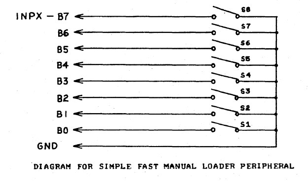
The device is connected to any input port with a standard SCELBI peripheral cable. There is already a pull-up on each input, so all that needs to be done, is to either leave the input floating, in which case the SCELBI’s internal pull up resister will pull the input level high or connect the input to ground, which will force the input low. The operator sets each input to a high or low state with a simple DPST switch.
The way this peripheral is operated is as follows. Using the front panel, the operator toggles the four byte long, fast loader program into memory, starting at location 0, and then sets the H and L registers to point to where the data needs to be written.
When run, the fast loader program will read the input port connected to the fast loader, writes the data to memory, increments the L register and then halts. Once the program is started, the operator enters a RST 0 instruction into the SCELBI front panel toggle switches. While still halted, the operator enters the data to be written into the next memory location into the fast loader toggle switches. The operator presses the interrupt button on the SCELBI front panel and then the run button. The program will jump to zero because of the RST 0 instruction that is set on the front panel. The program at location zero will read the input port, deposit the data to memory pointed to by the H and L registers, increment the L register and then halt again. The process is repeated until the operator has entered all the desired data into the SCELBI’s memory.
The fast loader program follows. This version assumes the fast loader peripheral is connected to input port zero, but other ports can be used by changing the INP instruction.
Line Addr. CodeBytes Source LineLine Addr. CodeBytes Source Line
—- —— ———– ———————————-
01 START:ORG 000#000
02 00-000 101 INP 000 ; read port 0
03 00-001 370 LMA ; save to memory
04 00-002 060 INL ; increment L
05 00-003 000 HLT ; stop
This program doesn’t handle the case of register L wrapping, but a few more instructions could be added to increment register H, if L wraps. Most boot programs should be designed fit into a single page, so this should not be necessary.
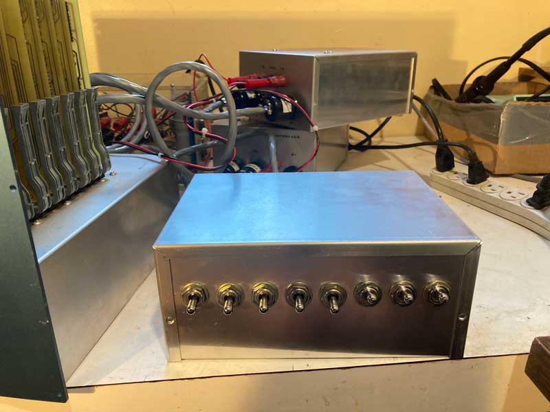
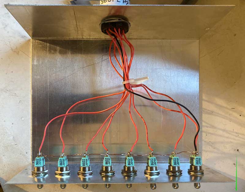
Here is a picture of the inside of the fast loader that I built. You couldn’t possibly come up with a simpler design for a peripheral device.
Hi Mike. Stumbled on your page today, great stuff!
I’m building a home brew cpu, about 95% 6502 compatible, from lsTTL chips. I had a rush of blood to the head this week and decided to aim for a 5.25 floppy as a means of getting simple software onto it. Nice steampunk feel to it.
I have an old Tandon drive and ordered a wd 1770 FD controller chip. Plan is to take a break and get the drive working with an ATMega328p.
So, I was wondering , did you ever finish your project to interface to the Apple Disk II? I have an old apple and drives that I built many a hack for, and thought maybe that might be the way to go.
Cheers
Con
nope, never finished that project, though I could read/write and format floppies on a Disk ][