I’ve had a couple more wiring sessions and only have something like 32 wires to go. I’m doing things a little differently than on the 8H and figured I’d share a few tips.
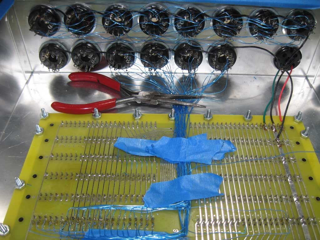
SCELBI Wiring in Progress
First of all, I’m not following the order listed in the SCELBI hardware manual. Here is the progression I’m going through, and why it helps.
First, I put in the ground wires. I’m using a little heavier gauge wire on that, and it’s a little less flexible. It’s easier to put in first, because I don’t have to work around all the data and strobe lines.
Next I put in the data output bus, wiring pins 1 through 8 from output socket to output socket. These wires are all the same length, so I cut and stripped these wires in batches. Then I did a batch of soldering. I’m not connecting this bus to the backplane, right now. I’ll do that near the end of this process.
Next step is the data input lines. Here I have almost completely reversed order from what is listed in the manual. Start with wiring the data bus to port 6. Then work down the line towards port 1. This way, the longer wires go in last, and you will not have to work over and around them, when you solder the shorter wires. The other important change is to wire bit 8 first, working around the connector to bit 1. If you wire from bit 1 to bit 8, as listed in the manual, the higher numbered bits will be harder to wire, because the wires to the lower bits will tend to be in the way of higher numbered bits. This time, I’m paying attention to the manual and using some painters tape to hold the wires down as I work. This keeps things much neater as you proceed. You’ll notice that I also have a needle nose pliers holding down the wires near the sockets.
The easiest way to connect the wires to the backplane, is to strip about 1/8″ from the end of wire and use a needle nose pliers to make a small loop, just larger than the size of the pin. Hook the loop around the backplane pin and hold the wire down with a weight of some sort. At that point, you can solder it using two hands and make sure there is no short and adjust it pretty easily. Lead the wire away from the post, and bend it with a needle nose pliers as it works its way to the I/O connecters. Use a piece of painters tape to hold it in place. Cut it to length. Then strip the end and use a needle nose pliers to curve it into a hook shape. Use the hook to connect it to the correct connector pin. This will help hold the wire place, which makes soldering easier.
The last wires I’ll do are the data output bus wires and the output strobes. I’ll do these last, so that those wires will not get in the way of the input wiring process which happens on the lower tier of connectors. I haven’t decided how I’ll route the output data lines, but I may route them directly to the output port on the end closest to the data buses location on the backplane.