
I’ve been working on writing detailed build instructions for the SCELBI Cassette Boards. I need to do this, because I haven’t found original build instructions. There have been a few challenges with the cassette boards, as the schematics haven’t always matched existing boards. Also, the initial version of schematics I had, were missing some labeling information on resistors and capacitors. I recently obtained images of some later schematics and got to examine a original board that help fill in some of those gaps.
My reproduction was built to match the earlier schematics and a couple of different boards that I had images of. As part of this documentation process I had a chance to compare an original board with my reproduction. Here is a side by side scan of my reproduction next to that original SCELBI write board.
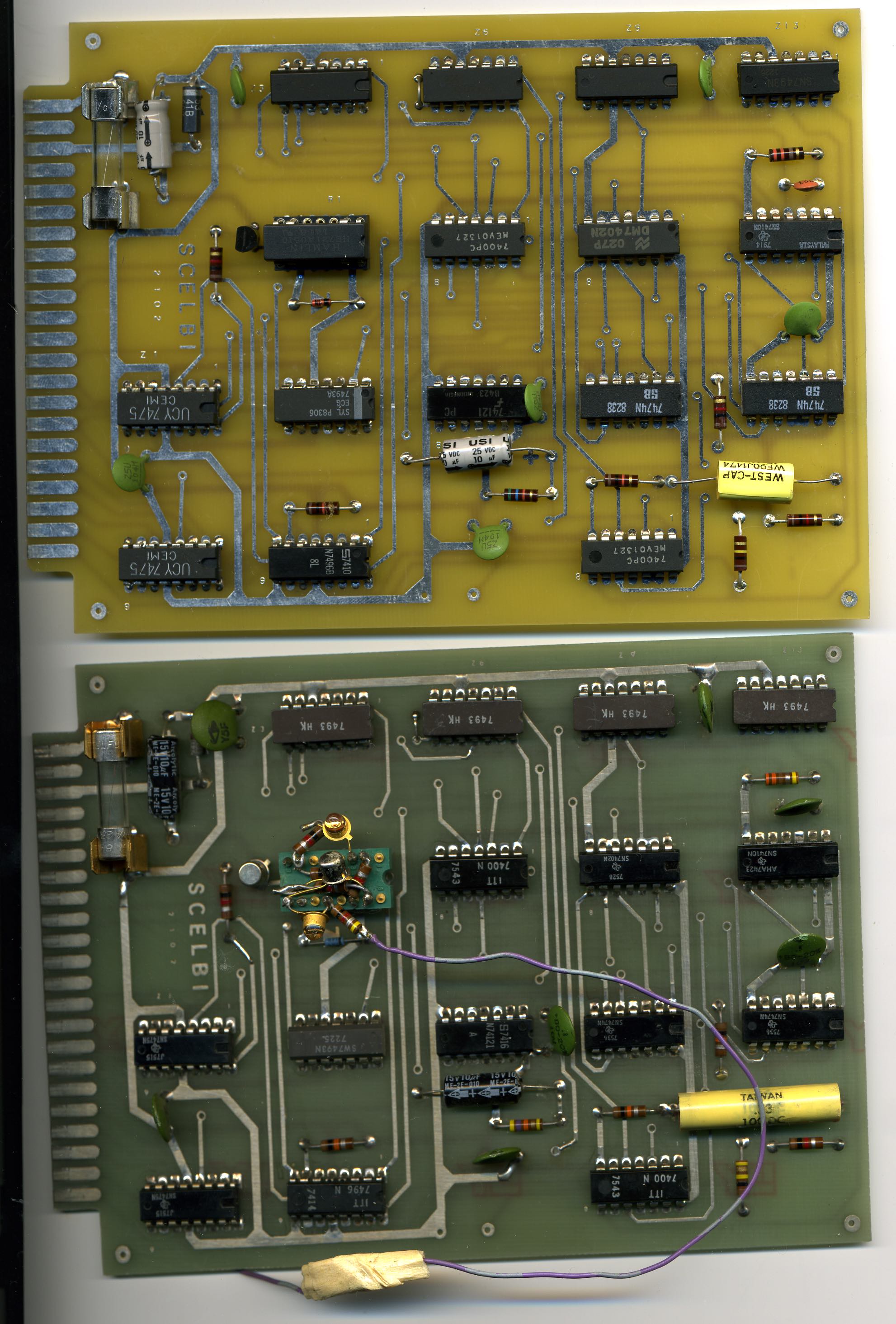
Original and Reproduction Write Card Comparision
You can ignore the circuit in the relay socket. That was put there for debugging purposes, way back in the 70’s. It was basically using LEDs to indicate when the RELAY circuit was activated. The different color substrate is due to evolution of technology. The old green substrate is no longer made, because it fluoresces which affects modern photo based PCB fabrication processes. Some reproduction guys are dying their modern boards to give their reproductions the old time look.
Going through the later schematics and this board revealed a few things.
Here is my current version of the cassette write board build instructions.
8B- Cassette Write board – build instructions
I tried to make them match the style of original SCELBI build documents. Note that I need to investigate a few more things including that reversed 10uF capacitor before finalizing this document.