
My previous post describes a little of the repair history of my Tektronix 465 and the recent failure of the trigger “A” level control after a spilt coffee event.
So now I had a Tektronix 465 that was completely useless. I figured that the coffee had penetrated into the trigger “A” potentiometer and caused an open or short in it. My experience with the trigger “B” pot indicated that I should be able to open it up and clean it out without too much difficulty. Whether I could restore it to proper functionality was another matter.
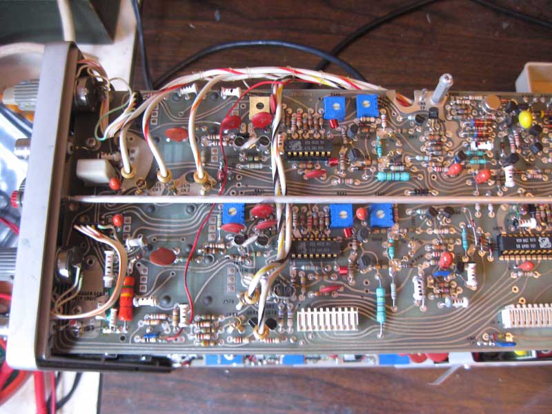
The 465 is easy to get into. Unplug the unit and remove the 6 screws on the back, 4 of which hold the feet on. Then slide the chassis out of the enclosure. The trigger controls are on exposed on the right side of the chassis. Both trigger controls can be seen on the left side of this image. This image also shows why I have been a bit nervous about troubleshooting this unit. A lot of discrete logic and individual wires running around doing mysterious things.
Trigger Card
The controls have dual functions in one unit. On the back is the slope switch, which is a simple on/off switch. On the front side is a 10K potentiometer. Removing the control from the chassis is easy. Use an allen wrench to loosen the screws holding on the knobs and remove them. Use a wrench to remove the nut and washer holding the control to the front panel. Unplug the wiring harness and you should be able to remove the control from the chassis.
Once removed, I tested the pot by using an DMM on ohms setting to check for dead spots or shorts. A 10K pot should show a gradual/steady progression as you rotate the control. Testing showed that this control clearly had issues as it reported open circuits in various postions. I decided to open it up and clean it out and see if I could restore proper operation.
I opened the control by gently bending back the tabs holding the control together. These are the tabs at the front of the control. Note that one of these tabs is not bent over by the factory. This tab is used to index the control to the front panel. This tab should not be bent back over, when reassembling the control. Don’t touch the ones at the back of the control, unless the switch part of the control is really messed up and you need to get in there to straighten it out. You have to be gentle bending these tabs back, as they are not intended to be opened. The metal will fail if you have to do this more than a couple of times or you are not careful with them. Once opened, the control will come apart. Be aware that the hardest part of putting it back together will be getting the switch portion properly engaged as you put everything back together. Try to pay attention to how the switch mechanism is set up, before everything comes apart.
I used a cleaning process that is very similar to what I have used on Datanetics mechanical keyswitches. I simply flooded the mechanism with isopropyl alcohol and rotated the wiper. After doing this a couple of times, I tested again with the DMM. After doing this, it appeared that it was operating correctly. I let it dry overnight and retested in the morning before reassembling the control.
I installed the control in the chassis and turned on the scope. Oh-no, now I didn’t get a trace. No matter what controls I changed, the only sign of a trace, was a small dot in the center of the screen. This dot could only be seen, if I turned the brightness fully up.
My first thought was that the coffee had migrated to somewhere else and now messed up the horizontal control circuit.
to be continued…