Easy TTY Emulation on an Apple ][e

Back in 2015, I partially described how I used an early Apple serial card in an Apple ][ to provide a “glass” TTY emulation in order to check out some of my SCELBI software and interfaces. Since I don’t have a real TTY, I always had to set up the Apple ][ and download an emulation program via cassette tape interface in order to test the SCELBI with an TTY interface. Over the years, this has been an annoying bit of hassle, mainly because I usually forgot exactly what version of the software that I needed to download, exactly where in memory to download it, and what slot to put the serial card into.

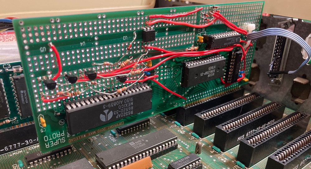
I knew that I could create a turnkey power on and go solution by designing and building a custom Apple ][ peripheral board. I just needed to copy the current loop interface from the Apple Serial card to a Superproto board and drive it with the Superproto’s 6522 VIA interface hardware. I knew I could easily port the program I had already written to run right out of the Superproto’s EERPOM. I first thought about doing this years ago.

Finally I started to do something at the beginning of this year, when I ordered the few required hardware components that I didn’t have in my stash. These parts came in right away, but, until now, I haven’t found the time to build up the board and port the software.

TTY Card
TTY Card

Well, I finally found the time to get this project working. I think the result is pretty cool. To connect a TTY with a 110 baud current loop interface to my SCELBI, I just connect the Apple ][e to a monitor, the SCELBI and power it up. No need to bother with floppy disks or cassette interfaces, or anything else. Since this card looks like a Disk ][ to the Apple, the Apple will automatically boot the TTY application, which resides in the Superproto’s EEprom.

I could potentially add logging, paper tape emulation and scroll back capability to this application, but I probably will not proceed with those ideas, at least anytime soon.

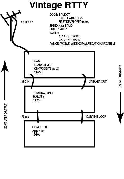
One other thing I might do, is create a version of software that will work at 45.45 baud and the Baudot charactor code, so I can use it with RTTY applications. I have done a simple version of this software for the Apple serial card, so it shouldn’t be too hard to port over. Since the Superproto supports multiple banks of memory in the EEPROM, I can use the same board and just put the RTTY app in a separate bank, and use the bank select jumpers to switch between TTY and RTTY applications.

Someday, I might make a custom card for this design, but I’m not going to do this unless I hear about some kind of demand for such a card.

Let me know if you are interested in seeing more details of the software and hardware design.

Can -47dB be equal to 60dB?

dB is usually used as a relative measure of power, so it all depends upon if the dB value on each side of the equation has the same relative base value.

My Kenwood TS-530S service manual specifies a signal generator as a required piece of test equipment. The specification is written as follows.

STAND SIGNAL GENERATOR (SSG)
1) Frequency range: 1.8 to 30 MHz
2) Output: -20 dB/0.1uV ~120dB/1V
3) Output Z = 50Ω

Later sections of the TS-530S service manual specify “SSG” settings as NNdB, where NN is the desired value. A typical setting seen in the manual would be 60dB.

My signal generator is a Marconi 2018. It’s RF output is specified as:

Level:
0.2 uV to 2 V e.m.f.; c.w. and f.m.
0.2 uV to 1 V e.m.f.; when a.m. is selected.

Selection:
By keyboard entry – units may be
(i) uV, mF, V, e.m.f. or p.d. or
(ii) dB relative to 1 uV, 1 mV, 1 V, e.m.f. or p.d. or
(iii) dBm

It is specific as expecting 50 ohm impedance, same as the TS-530S.

However, there is no mention of -20 dB/01.uF or ~120dB/1V in the Marconi manual, so I needed to figure out how to covert from Kenwood TS-530S service manual settings to Marconi settings. First, I decided to use the default dBm setting on the Marconi, since that is a pretty standard usage for dB in the RF world.

I’m interpreting the -20dB/0.1 uV value in the TS-530S spec as meaning that 0.1 uV should be interpreted as -20dB.

You can manually do the following equations, but I find these sort of jobs are more easily done by finding and using an online calculator. Using the online calculator at http://www.eeweb.com/toolbox/rf-unit-converter, I entered 50 Ohm impedance and .1 uV Voltage. This returned a value of -127dBm Power. This means that at -20dB(TS-530S value), the dBm Value is -127, a difference of -107.

Leaving the 50 Ohm impedance, I entered 1000000 in the uV Voltage box, which returned 13 dBm. This means that at 120dB(TS-530S value), the dBm Value is 13. Once again a difference of -107.

This consistent difference in value makes sense, since dB is a relative value. So now I knew that I could simply subtract 107 from any value in the TS-530S service manual in order to know what value to program into the Marconi 2018. A typical signal generator setting in the TS-530S manual is 60 dB. I would calculate the Marconi signal generator value by subtracting 107, getting a -47. So yes, -47dB can be equal to 60 dB.

Posted in HAM

Apple II TTY Emulator Fixed

My previous posts described some barely working attempts at using an Apple IIe as a teletype replacement. When faced with bringing up my SCELBI cassette interface, I decided I needed to improve the Apple II based TTY emulation system.

After spending about a week of my spare time focussed on this effort, I think I succeeded pretty well. The hardware interface hasn’t changed from that previous post, but the TTY emulator now supports the standard SCELBI TTY software and hardware really nicely with full 72 columns and 24 lines. Most of that time was spent trying to overcome what appears to be a glitch in the hardware serial start bit detection.

Except for the initialization routine, I bypassed the Apple monitor character out functions and ended up writing my own output functions. Control characters behave like the SCELBI MEA application package expects them to behave. With the full screen now available, the new TTY emulation software is much more pleasant to use than the previous version.

I didn’t implement a cursor. Some people may feel this is a shortcoming. While a cursor would be pretty easy to implement, I decided that a real TTY didn’t have a cursor, so my emulator shouldn’t need one, either.

If you are interested, the source code can be found at this link:http://www.willegal.net/appleii/ttyemul-fs.asm

While working on this, I found one little issue with the MEA memory dump command. When dumping a full line of memory contents, it attempts to print a space character in column 73 of the TTY. I’d guess that a real TTY would just refuse to advance the carriage in this event. If you know how they really work, let me know.

I’ll need to port these changes over to my RTTY application, so it can also use a full screen. It’s not directly usable, because the RTTY runs at 45 baud and uses Baudot, instead of 110 baud ASCII. In any case, the RTTY port will have to wait, as next up on the to do list, is to check out the SCELBI cassette interface cards, which are built and waiting.

Apple IIe Fast Scroll Routine

I’ve been working on improving my Apple IIe TTY emulation application. One of the major limitations with it, is the amount of time it takes to scroll the Apple IIe’s screen, especially when in 80 column mode. In order to improve this function, I wrote my own fast scroll routine. Kind of interesting how close it turned out to a comment I received to a previous post, even though I forgot about that comment by the time I did this.

;
; Fast Screen Scroll Routine
;
LINE1 EQU $400
LINE2 EQU $480
LINE3 EQU $500
LINE4 EQU $580
LINE5 EQU $600
LINE6 EQU $680
LINE7 EQU $700
LINE8 EQU $780
LINE9 EQU $428
LINE10 EQU $4A8
LINE11 EQU $528
LINE12 EQU $5A8
LINE13 EQU $628
LINE14 EQU $6A8
LINE15 EQU $728
LINE16 EQU $7A8
LINE17 EQU $450
LINE18 EQU $4D0
LINE19 EQU $550
LINE20 EQU $5D0
LINE21 EQU $650
LINE22 EQU $6D0
LINE23 EQU $750
LINE24 EQU $7D0

FAST_SCROLL
  STA STORE80 ; enable aux mem
  STA PAGE2OF ; page 1 first
  JSR FS_DOIT
  STA PAGE2ON ; now do aux mem

FS_DOIT:
  LDX #39
FS_L1:
  LDA LINE2,X
  STA LINE1,X
  LDA LINE3,X
  STA LINE2,X
  LDA LINE4,X
  STA LINE3,X
  LDA LINE5,X
  STA LINE4,X
  LDA LINE6,X
  STA LINE5,X
  LDA LINE7,X
  STA LINE6,X
  LDA LINE8,X
  STA LINE7,X
  LDA LINE9,X
  STA LINE8,X
  LDA LINE10,X
  STA LINE9,X
  LDA LINE11,X
  STA LINE10,X
  LDA LINE12,X
  STA LINE11,X
  LDA LINE13,X
  STA LINE12,X
  DEX
  BPL FS_L1

  LDX #39
FS_L13:
  LDA LINE14,X
  STA LINE13,X
  LDA LINE15,X
  STA LINE14,X
  LDA LINE16,X
  STA LINE15,X
  LDA LINE17,X
  STA LINE16,X
  LDA LINE18,X
  STA LINE17,X
  LDA LINE19,X
  STA LINE18,X
  LDA LINE20,X
  STA LINE19,X
  LDA LINE21,X
  STA LINE20,X
  LDA LINE22,X
  STA LINE21,X
  LDA LINE23,X
  STA LINE22,X
  LDA LINE24,X
  STA LINE23,X
  LDA #$A0 ; clear last line
  STA LINE24,X
  DEX
  BPL FS_L13

  RTS

This routine takes about 18 milliseconds to run on a 1 MHz Apple IIe, compared to the standard monitor scroll routine which takes 34 milliseconds. Other than unrolling the loops, which would greatly expand the size of the function for a minimal speed increase, I think this is about as fast as it’s going to get.

18 milliseconds is still not fast enough for my TTY emulation package, so I’m going to have split it up into several segments and check for input events between segments. However, now that I have my own version of the scroll code, I’ll be able to split it up relatively easily.

There are some other issues with the standard monitor COUT routines for this TTY application, so it’s very possible that I’ll end up customizing all the COUT routines. For instance, I’ve already customized the “BELL” function for performance reasons. The Carriage Return function also had to be customized, because on a teletype, CR does not force a line feed.

Radio Teletype Explored – part 1

Before I acquired Chris Galfo’s HAM software package for the Apple II, I had already developed a simple RTTY (Radio Teletype) setup that used my Apple IIe as a terminal. This series of posts will go over what I did to put together this setup. Before going into details of each component, I’ll go over the general setup and a few of the decisions that lead to the choice of major components.

In the beginning, my goal was to set up a RTTY station using 70’s era components. As you will see, I went a little into the 80’s in the choice of some specific components, but the basic platforms on which those components were based, were all available in the 70’s.

RTTY Block Diagram

RTTY Block Diagram

As you can see, my setup is made up of 4 main components.

  • The antenna – I’m currently using a simple inverted V dipole because of ease of deployment and low cost
  • The radio – Kenwood TS-530S – I chose this unit as it is an vintage unit that is an evolved version of a Kenwood TS-520. The TS-520 was released about the same time as the SCELBI-8H, but my TS-530S was sold in the early 80s. I chose the TS-530S over the TS-520 primarily because of it’s integrated digital frequency display and support for additional bands
  • The TU (teminal unit) – HAL ST-6 – The main job of the terminal unit is to convert tones coming from the radio audio output to a series of 1s and 0s which is digital information that can be interpreted by a computer or teletype. It also can convert 1s and 0s coming from a teletype or computer to tones to be sent to a radio’s microphone input for transmission. The HAL ST-6 was released about 1970 and still has a reputation as being one of the best terminal units around
  • The keyboard and display unit – Apple IIe – I choose this over the SCELBI because of the integrated video display and keyboard. I chose the IIe over earlier Apple II models, because it has an integrated 80 column display. Teletypes have 72 column output, which would require 2 lines to display on a standard 40 column Apple II display. I explored using a straight Apple II with a plug in 80 column card, but found some differences between the 80 column support in an Apple IIe and the standard Videx 80 column card. Turns out the differences were significant for this application, so I went with the Apple IIe
  • First of my “Vintage Digital Radio” Webpages is Up

    This is the first of several webpages that I plan on putting up to document my efforts to integrate vintage computer operation with present day HAM activities. It is not currently linked to from my main homepage or other vintage web pages.

    This page provides access to one of the first commercial HAM communications packages to be released anywhere. During my explorations of HAM integration with early vintage computers, I ran across several references to a software program released by a CH Galfo. Though I couldn’t find any actual images of the software or documentation, I was lucky enough to make contact with Dr Galfo, himself. Better yet, he was friendly and willing to help make the software accessible to vintage computer people. He sent me a floppy and a hard copy of the documentation, both of which I’ve been able to copy into a web friendly format. Dr Galfo indicated that since there is no commercial value, that you should feel free to copy and distribute.

    http://www.willegal.net/digitalradio/Galfo-HAM-App.html

    VCF east/X highlights

    What a awesome time. Here are some highlights.

  • First of all, thanks to everyone at MARCH for putting on a great event. I felt that this interation of VCF east, was the best ever.
  • Great speakers – Brian Kernighan and Bob Frankston
  • The variety of systems present and running was very impressive
  • An especially large number of PDP-8s of different vintages were present. Makes me want a mini for myself, or at least get my ancient printout of collosal cave OCR’d, compiled and running on something
  • It was very nice to meet all the HAMs, old friends, helpers and visitors
  • Too much RFI, a poor antenna situation, and poor conditions prevented actual communications during the show, but I was able to cheat and display a SCELBI decoding morse generated out of a PC sound port and an Apple IIe decoding the RTTY feed from rtty.com – more about this coming soon in my blog and website
  • I had my first piece of equipment die at a show. My Apple Monitor II’s fuse blew towards the end of the day on Saturday. A quick investigation didn’t reveal anything obvious, except high current draw. Thanks to Ian and Jeff for taking the time to help me take an initial peek at it. This is my only monitor that has really acceptable 80 column output, so I’ll have to continue to work on figuring out the root cause and get it back to 100% health
  • The number of simulated platforms surprised me. I’m calling a simulated platform, a physical piece of hardware platform that at it’s core, is made up of a more modern processor, like an Arduino or Raspberry Pi. The number of people using modern technology to restore or simulate vintage hardware is growing fast
  • As always, I wish I had more time to spend at other peoples nifty exhibits
  • Reason for Lack of Posts this Month

    I’ve been busy working on my VCF east exhibit.

    It’s about the relationship between HAM radio and early personal computers. I have lots of interesting things to blog about. However I want to unveil my discoveries and experiments at VCF east, rather than reveal the exhibit contents ahead of time through blog posts.

    Come to VCF east next month, and you’ll get the first look at what I’ve been busy working on. Sometime during or after VCF east, I plan on putting up some web pages and will have quite a backlog of stuff to blog about.

    Infant Mortality?

    If a 40 year old, NOS, IC dies after a few hours usage, should it be considered infant mortality?

    glossory:

  • IC – integrated circuit
  • infant mortality – a term used to describe an electronic product that has a terminal failure soon after being put into use
  • NOS – new, old stock – an old part that hasn’t been used and is essentially is new condition, except for shop wear
  • shop wear – physical wear that can occur to an item that is on the shelf in a store or in storage in a warehouse
  • terminal failure – a failure that precludes using the item for it’s intended purpose
  • Corey,
    Thanks for the inspiration for this post – too bad you were bitten.

    Textronix 465 repair – part IX

    If you haven’t been following my blog, you should go back to the first post of this series, in order to get caught up.

    My treasured Tektronix 465 is now as healthy as a 35 year old electronics device could be. What did I learn from all this.

  • Some of the problems encountered during the repair, were of my own doing. That is not that unusual and is to be expected when one is attempting to learn how to repair something that is a bit out of their comfort zone.
  • In the process of doing this repair, I learned quite a bit about how this device works. I think that this will benefit usage of the tool going forward. For instance, I have a much better understanding of the “B Dlyd” trigger than I did before. I have used the “B” trigger pretty frequently in the past. However, with the additional knowledge that I’ve gained, I should be able to put it to even greater use.
  • Repairability of this generation of equipment is still good. Even though some of the repair parts are getting hard to find, with persistence, they can be had at an affordable price
  • Though I sometimes think I should get a newer scope with digital storage, it’s hard to find a great deal on anything with 100MHz bandwidth and multiple channels. For instance, the low end Rigol 100MHz, 2 channel scope sells at near $400.
  • And here’s something I’ve known for a while. While the Tektronix 465 is a 2 channel scope, the external trigger modes almost get you the equivalent of 3 channels. If you have a simple trigger, you can connect that to the trigger “A” external input and look at two other signals with the regular channel 1 and 2 inputs. You know when the trace starts the external trigger condition was satisfied, so you pretty much know what that third signal is doing, without even seeing it on the screen.
  • Repairing this scope was an fun learning experience and I’m glad I spent the time to dig into it. Though there are a lot of discrete components involved, thanks to the excellent service manual, debugging it readily wasn’t that much different than debugging a digital system. Finally, I hope I don’t have to try to fix it again, for a good, long time.

    I hope you enjoyed reading the these blog posts and I encourage the reader to provide feedback by submitting comments.