
Sorry about the delay in getting this posting up. It was delayed while I waited for a replacement part to ship from Canada. It has now arrived so I can continue the Saga.
If you haven’t been following my blog, you should go back to the first post of this series, in order to get caught up. I had everything working, except for the “B” trigger slope control.
At this point, I decided to reconnect the external trigger input. I wasn’t quite sure how it was connected. Fortunately, I had taken a photograph of the connection before disassembly.
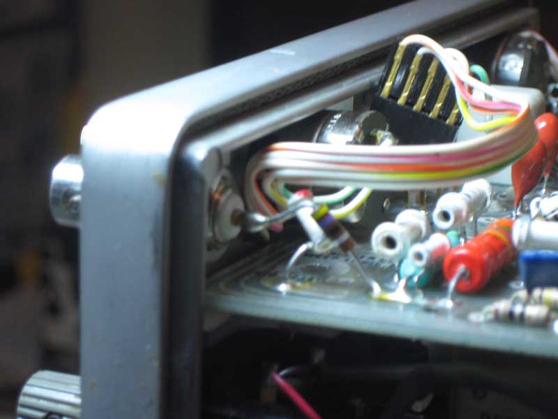
External Trigger Wiring
Though the picture wasn’t in focus, it was good enough for the purpose and I was able to reconnect the external trigger and test it successfully.
The slope control is fairly simple in function. It provides an basic input to the trigger amplifier chip, as can be seen in the schematic.
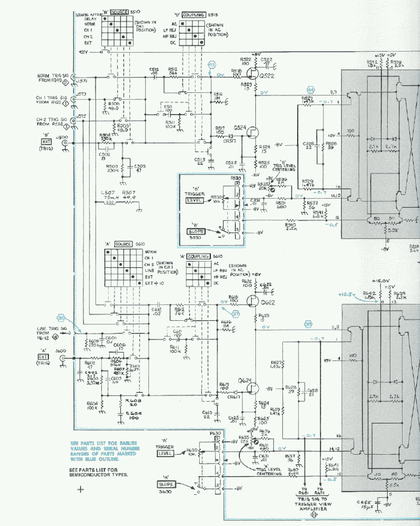
Trigger Input Schematic
The “B” trigger and “A” trigger circuit are very similar. I was able to verify operation of the slope switch and the input to trigger amp chip by comparing the two circuits. After finding no difference, I decided to swap chips. Sure enough, now the “A” trigger was stuck triggering on down slope and “B” trigger now worked on either slope. The problem was a bad trigger chip.
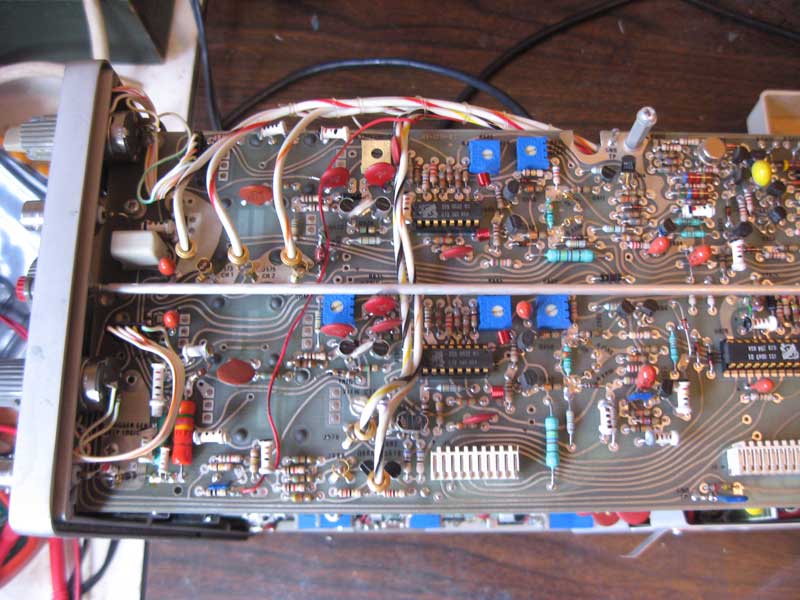
Trigger Card
The difficulty with finding a new one, is that this is a custom Tektronix chip. After finding several expensive sources on the internet, I was able to negotiate a deal with someone who was selling the entire trigger board. It took a while before I recieved the new chip and was able to install and test it. After installing, both triggers now worked on both slopes, and my Tek 465 was running sweeter than ever.
Do you remember, the 4.7uF capacitor that I had hacked in place of the bad 10uF capacitor? Before closing up the the scope, I needed to find a proper replacement. In a nearby shop, I found a radial 10uF electrolyic capacitor that I figured that I would be able to substitute for the original axial capacitor. This one had a 25 volt voltage rating, so I figured that it would last longer than the original, which was only rated at 10 volts. First, I removed the temporary 4.7uF capacitor. I bent the ground lead over on the new radial capacitor so it ran parallel to the body. I used a couple of short pieces of shrink wrap to hold the lead in that position. I then cut the leads to proper length and soldered the replacement capacitor in place.
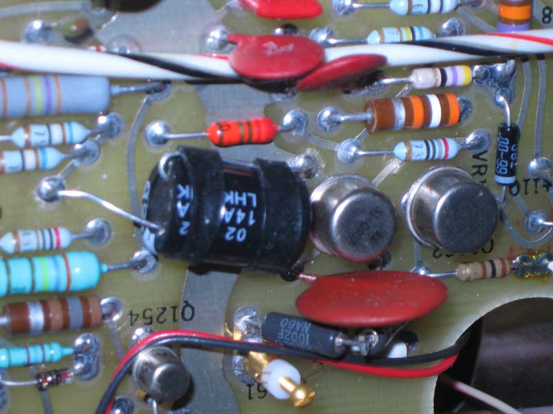
Replacement Cap
There were two more things about this scope that bothered me, that I haven’t mentioned, yet. One just came to light during the testing of the trigger repair and the other has been a concern since I owned the scope.
To be continued…