
If you haven’t been following my blog, you should go back to the first post of this series, in order to get caught up. I had everything working, except for a couple of things that I wasn’t sure about.
During testing of the “B” trigger circuit I tried triggering on the “B” trigger external input. This is something that I had never had a need to try since I owned the scope, so I wasn’t sure about how it would work. I failed to be able to trigger from it. After replacing the “B” trigger chip, I investigated further and realized that it wasn’t connected to the trigger board and another wire was in the location that it was supposed to be soldered to. Immediately, I realized that I had reconnected a wire incorrectly when putting the trigger board back into the chassis. This was the lone red wire in the image shown below.
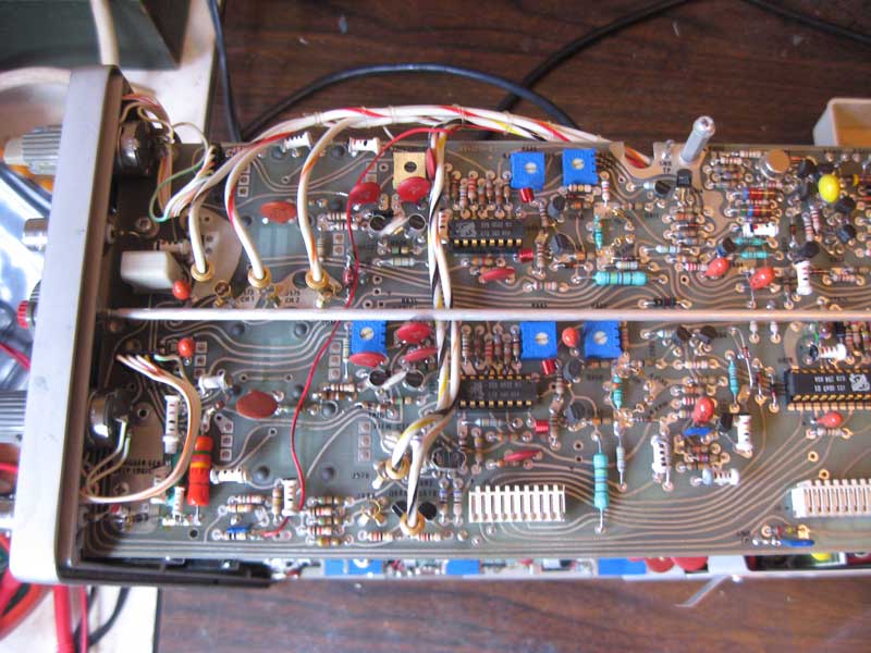
Trigger Card
Fortunately I had this picture that I took before taking it apart that showed where it was supposed to run to. I moved that wire and connected the “B” external trigger input and now the “B” external trigger worked. Thank heaven I took those pictures.
The second “issue” was a concern that when intensity is turned all the way up, a “dot” can be see on the screen even when the scope wasn’t triggering. I reviewed the the service manual, and found that the intensity circuit is additive, so this was possibly normal. I checked voltages in this section and a few other items and everything seemed close to spec. Finally, following service manual instructions, I adjusted the CRT bias down just a bit. After I couldn’t find any issue with the circuit, I have come to the conclusion that the design is working properly.
At this point, I think the Tektronix 465 is working fine in all respects. I’ll finish this series with one final posting recapping some things I learned during this adventure.
To be continued…