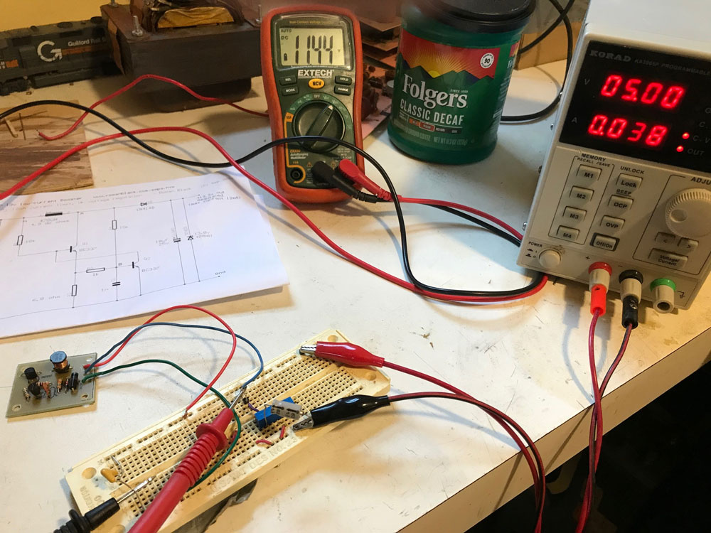
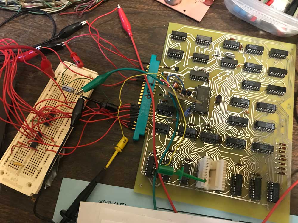
I’m making some progress on the Digital Group video card debug, but it has been a bit more difficult than I expected. First I had to connect it to my SCELBI and write a short program to test it with. Here is the test setup.
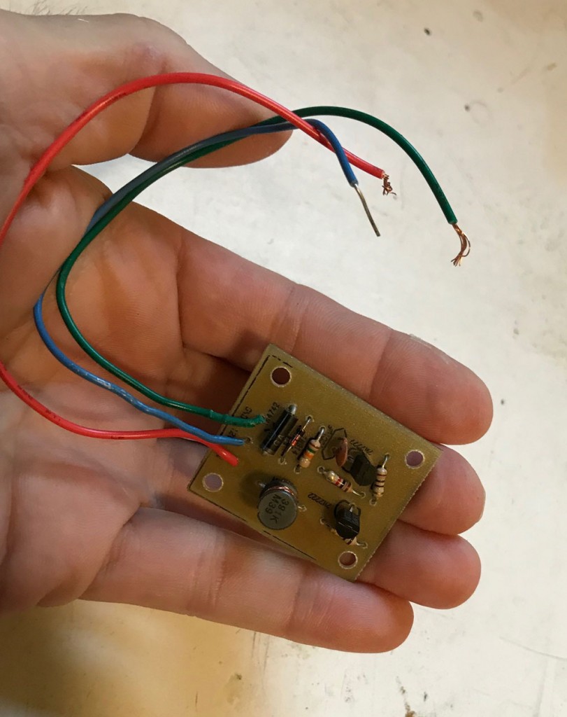
I needed to add an 8 bit latch in order to latch the SCELBI output port. This was easily accomplished with 2 7475 four bit latches and a bread board that I had in my parts bin. If I was thinking ahead, I would have added it to the PCB that contains the +5 volt to + 12 volt converter. Now I’m going to have to add another board to the final chassis design in order to hold the 8 bit latch.
The 5 volt to 12 volt converter is resulting in 11.96 volts at the MCM6571. That is nearly spot on, so it looks like that effort has paid off. One other thing to keep in mind when wiring the power for peripherals on the SCELBI, it’s pretty important to avoid ground loops and run power and ground directly back to the power supply. It’s tempting to use the ground wire on the peripheral cable, but it’s best not to do that.
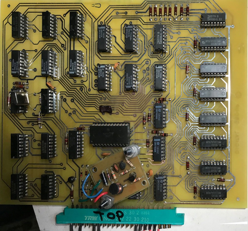
Debug has been a bit slow, and I found a couple of assembly mistakes on the PCB. First, I put capacitor C8 in the wrong holes which caused problems with the R/W output of U-23. The second mistake was forgetting to solder the ground pin of the 6571 character generator. I also had a bad 74193 in the circuit that was used for writing to video memory. In this build, I used sockets, so testing and replacing the 74193 was pretty easy.
The documentation suggests that a user could use a second output port and directly address video memory, rather than use the counter solution. Given that there usually is no shortage of output ports on the SCELBI, this might make a better solution for the SCELBI. It would be fairly simple to replace the two 74193 counters with 7475 latches in order to achieve this.
During this process I wrote two short programs for debug. The first one puts the same character in every location in memory. This was helpful when I was having trouble writing to memory. Putting the same data in every location made it easier to tell whether writes to the 1101 memory were working or not.
000 000 ORG 002 000
002 000 016 000 STRT, LBI 000
002 002 006 301 CONT, LAI 301
002 004 161 161
002 005 044 177 NDI 177
002 007 161 161
002 010 010 INB
002 011 301 LAB
002 012 074 000 CPI 000
002 014 110 002 002 JFZ CONT
002 017 000 HLT
002 020 104 000 002 JMP STRT
002 023 END
The second program writes every possible character to the screen memory.
000 000 ORG 002 000
002 000 016 200 STRT, LBI 200
002 002 301 CONT, LAB
002 003 161 161
002 004 044 177 NDI 177
002 006 161 161
002 007 010 INB
002 010 301 LAB
002 011 074 177 CPI 177
002 013 110 002 002 JFZ CONT
002 016 000 HLT
002 017 104 000 002 JMP STRT
002 022 END
These programs were both short enough that I just toggle them in through the front panel, rather than worry about setting up a TTY or scope and run MEA or MCMON.
The display with the second program loading up memory with a range of characters currently looks like this:
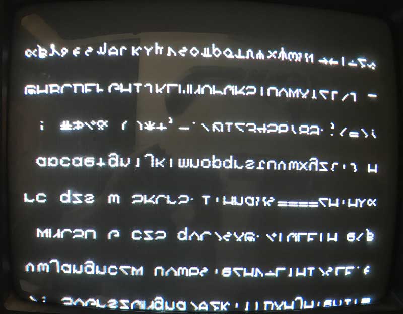
So the good news is that the horizontal and vertical sync is looking pretty good. In fact, given my concerns about the PCB layout, the video is downright crisp, much better than the Apple 1 or Apple []. I’m pretty impressed. The bad news is that the characters are all displayed upside down and clipped at the bottom. I’ll have to figure that out in my next debug session.
UPDATE: I just figured out that my reversed character problem is that I’m using a MCM6571A part which has a different/reversed decode when compared to a regular MCM6571. With character generators, you have to be careful about versions of the part and I guess I didn’t pay enough attention in this case.