Guarding the Dictator Mortar

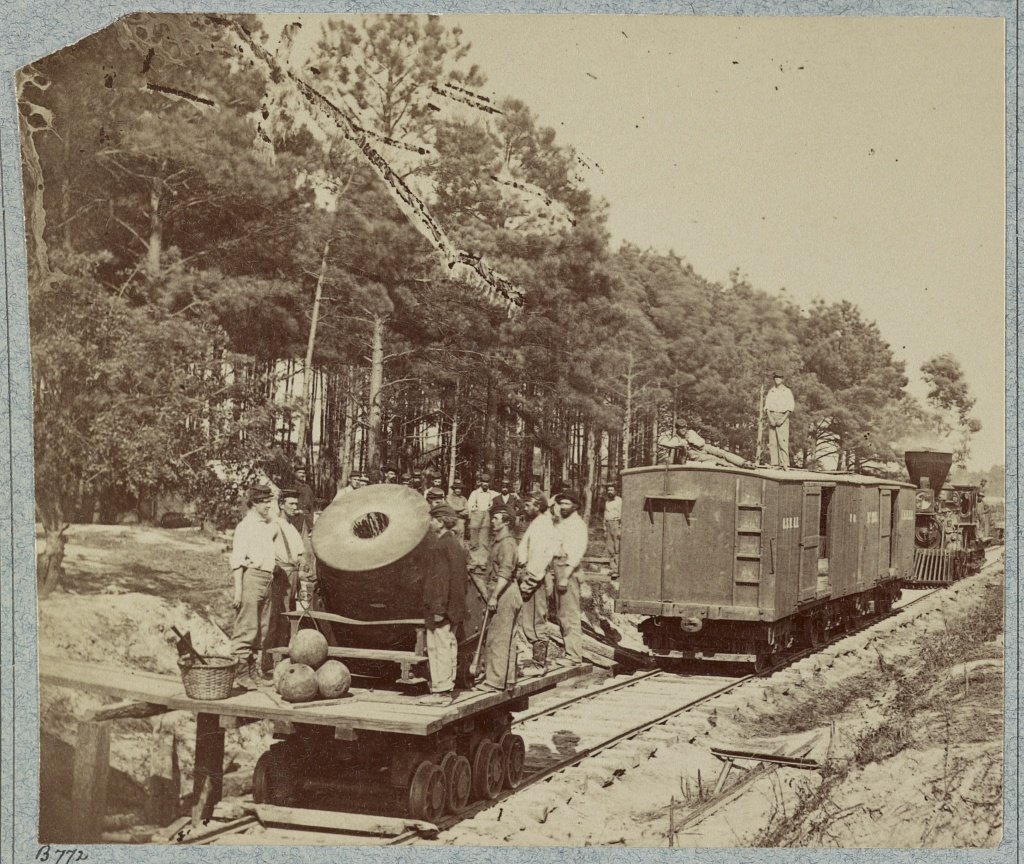
The Dictator was a 13 inch siege mortar used to bombard Confederate positions around Petersburg in the summer of 1864. It was mounted on a specially constructed flatcar so it could be moved around easily. It was initially used to silence a Confederate artillery position across the Appomattox River from the Union right. Until this position was silenced, the Confederate artillery enfiladed the right end of the Union line and made life especially difficult for the Union troops stationed in the trenches there. The Dictator was pulled out of the front line service on September 28, 1864 and put in reserve at the base at City Point.

The Mortar Dictator in front of Petersburg

However that isn’t quite the end of the story. This letter found in the National Archives indicates that as late as December 4th, 1864, some men, which came from the 1st Connecticut Heavy Artillery regiment were still watching over her.

Mortar Guards Letter

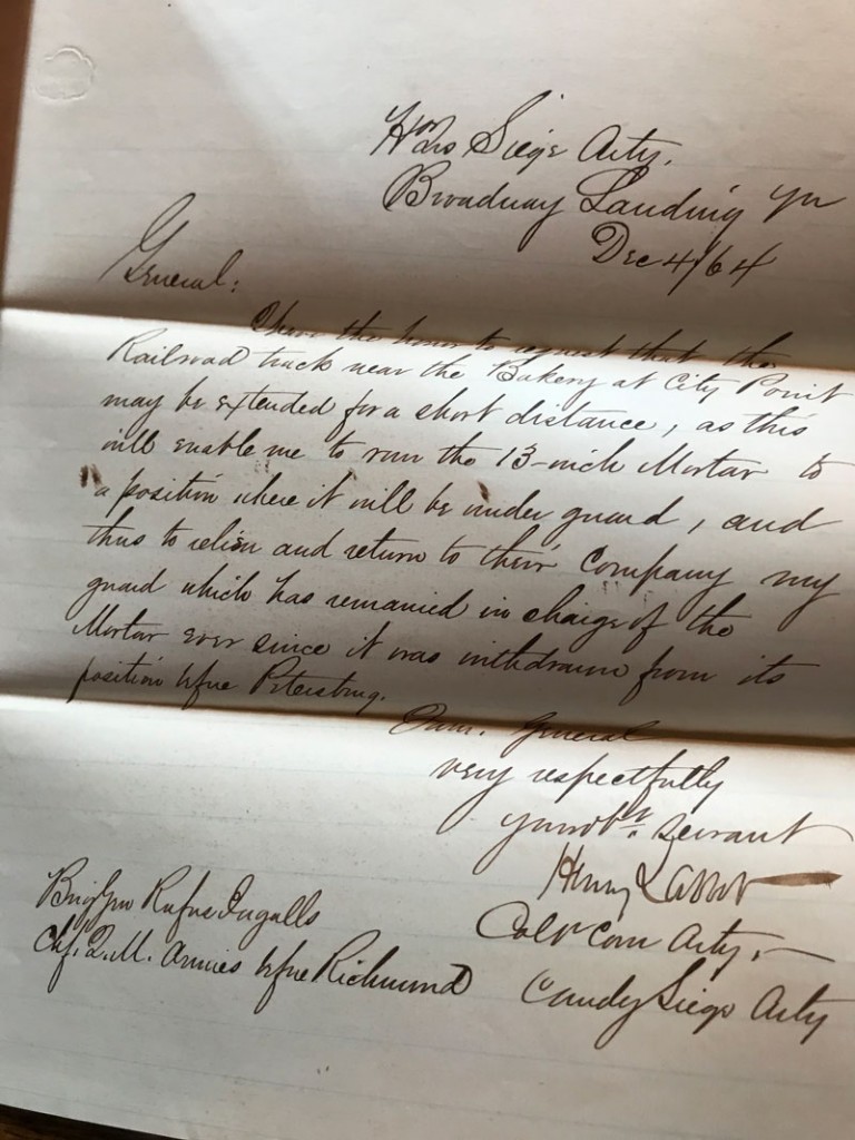
Here is the text of this letter to Rufus Ingalls, who was the Chief Quartermaster for all the Armies before Richmond..

Headqua. Siege Arty.
Broadway Landing

Dec 4th, 64

I have the honor to request that the Railroad track near the Bakery at City Point may be extended for a short distance, as this will enable me to move the 13-inch Mortar to a position where it will be under guard, and thus to relieve and return to their Company my guard which has remained in charge of the Mortar ever since it was withdrawn from it’s position in front of Petersburg

very respectfully
Your ob. servant
Henry Larcom
Col. Conn. Arty.
Commander Siege Arty.

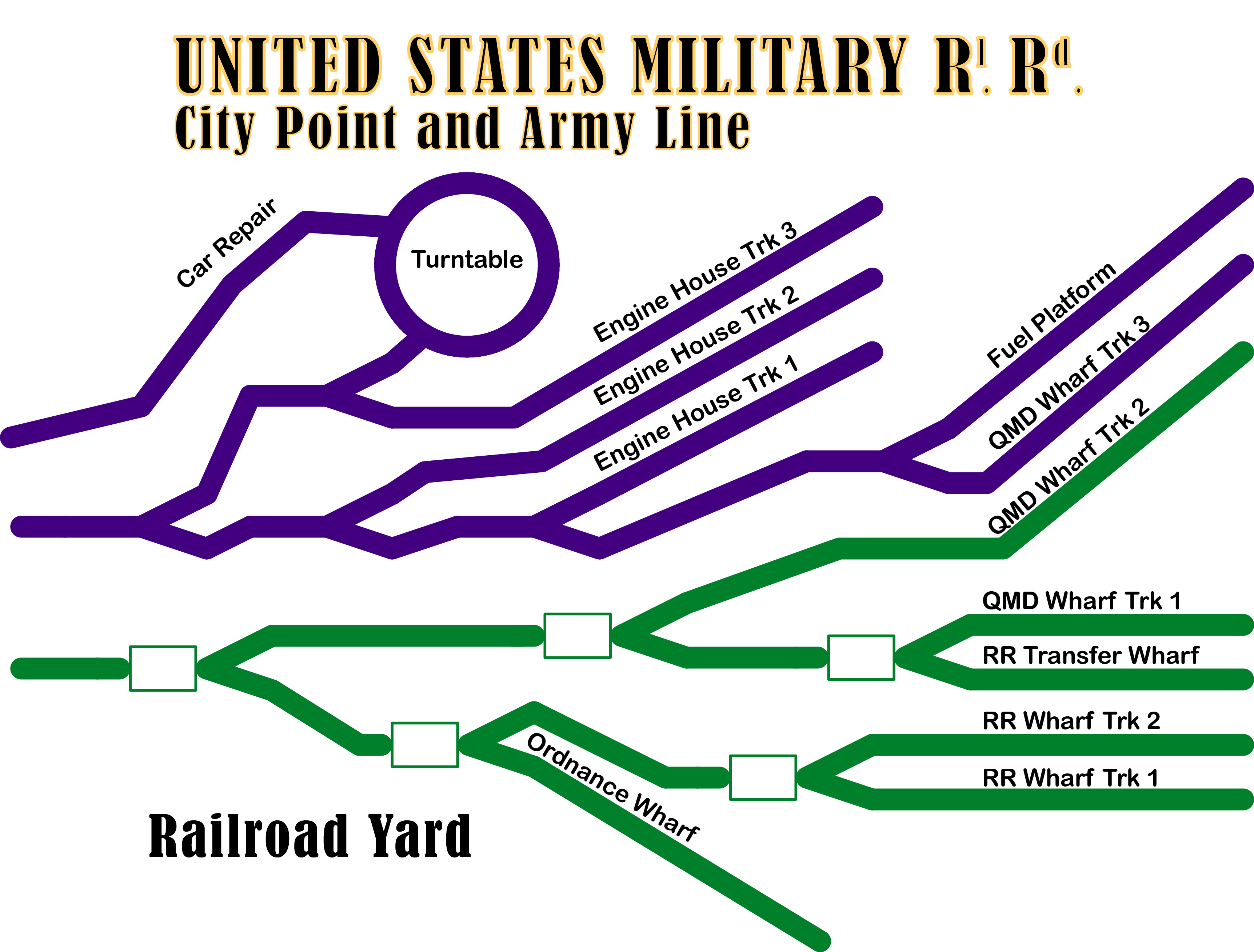
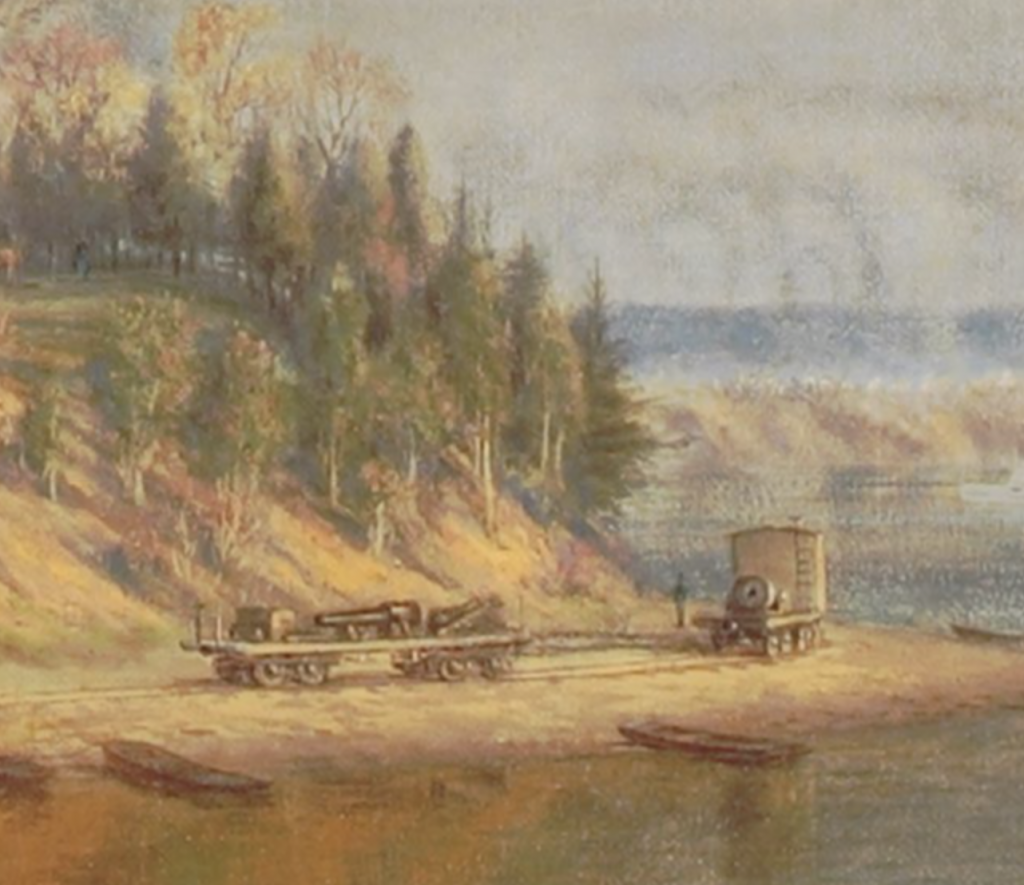
Note that E.L. Henry’s painting of City Point shows the Dictator positioned in an altogether different location, at the end of the tracks serving the Quatermaster Department Wharves. It likely that this is where the Colonel’s men were spending their time watching her. Note that Henry even painted a guard next to the mortar.

Dictator at City Point

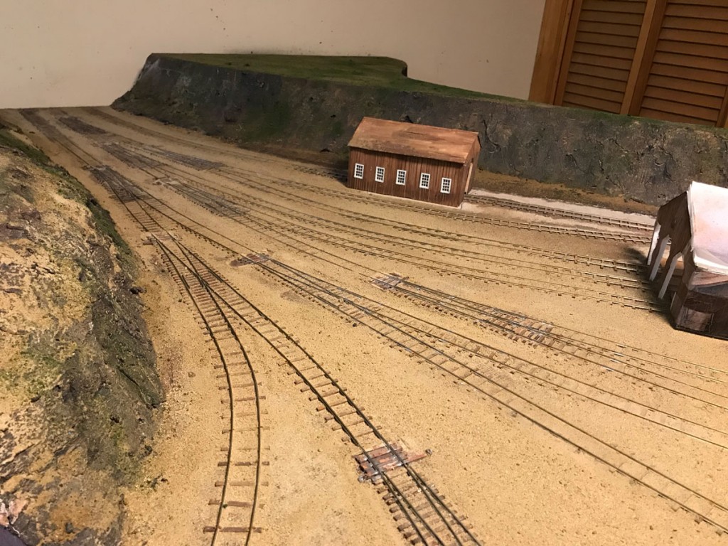
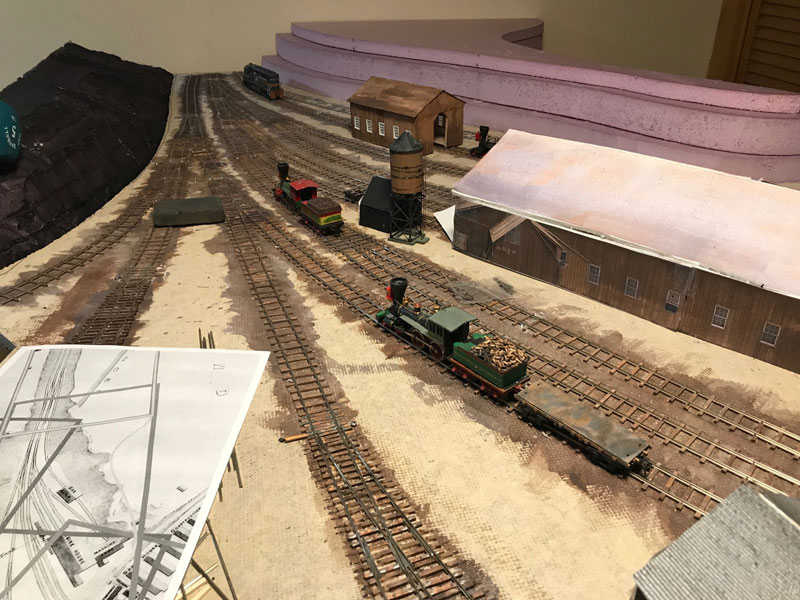
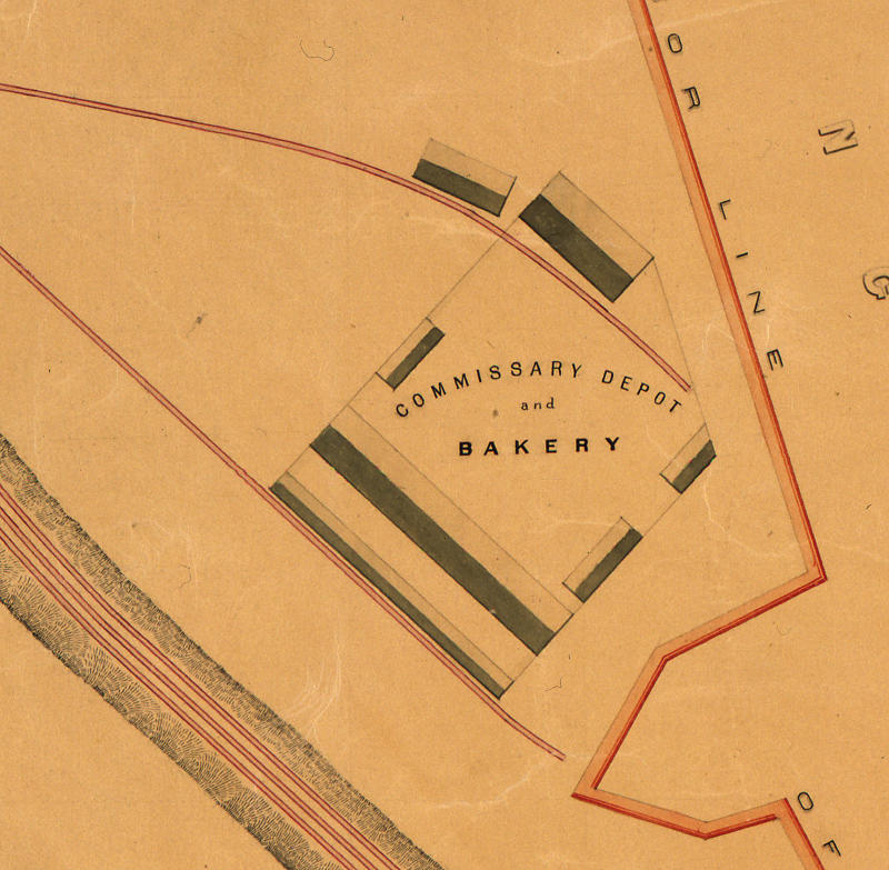
Looking at the map of the City Point railway, which was drawn after the war, shows that the bakery tracks do extend a bit past the end of the bakery buildings. It’s clear that if the Dictator was positioned there, it could be guarded by the men manning the City Point defensive line. Whether this is the extension that was requested or not and whether the Dictator ever ended up at this extension of the bakery tracks is unknown to me.

City Point Bakery
City Point Bakery

Though this little investigation of mine has little importance to anything or anyone, it is fun to see what can be found out about such trivial issues.

City Point Railroad Yard Ballast

Railroad Yard Ballast and Dirt

Most of the railroad yard now has ballast and dirt installed. The bluffs also have basic ground cover in place. The dirt comes from a yard of clay that I had purchased for use in a horseshoe pit.

For model railroad purposes, I baked it in an outdoor BBQ in order to kill any living organisms and then sifted it. The baking also removed excess moisture, which made it easier to sift.

I think the clay looks great in this application. My last model railroad used commercial ballast, which appeared oversized and too light in color to me.

Next part of the project is to clean up the track and get the switches moving freely again. I then need to wire the switch machines to the control panel and get all the switches and track operating.

When I get the track issues all straightened out, I will move onto installing the car repair shed. After that, I will finally be able to focus on the centerpiece of this module, the engine house.

City Point Railroad Progress

City Point Bluffs under construction

The bluffs are going up on my model railroad. You can’t really tell from this image, but it’s making a vast difference in the the appearance of this incomplete module. This really gives me motivation to move forward to see how it’s going to look with some more scenery in place.

Framing for City Point Engine House

City Point Engine House Frames

City Point Engine House Frames

I’ve been slowly starting to construct the frames for the City Point Engine House. At the top of this image is the queen post section of what will become an interior frame. At the bottom is one of end sections. First, I cut all the lumber to length. In order to get consistent results, I use an acetate sheet to hold the beams over a scale image of the framing while glueing together. The glue does not stick to the acetate which, once the glue drys, allows me to “peal” the acetate away from the wood frame.

A Little Progress with City Point Structures

Buildings Under Construction

Buildings Under Construction

I have one wall on the car shed, and it is starting to look like a real model. This wall went on a lot easier than I expected. I still have to stain it, and add battens to the siding, but I’m starting to think that the end product might turn out OK, despite the steep learning curve that I’m going through. In case you are wondering, I’ve designed these buildings to use Tichy Trains’ #8024 6 over 6 double hung windows, which seem to be a pretty close match to what I see in the pictures of City Point.

I’m learning a lot building the City Point car repair shed. The most important thing is, without a jig, cutting beams to consistent length can be very difficult in a HO scale world. I ended up buying a Micro-Mark Chop-It in order to make cutting the beams for the City Point engine house, a much easier, more consistent effort. While not the most precise device in the world, I’ve been able to cut quite a few beams for the engine house in one sitting, as you can see on the right hand side of the picture.

I’ve also going to try a different order of construction for the engine house. Rather than use the big beams to connect each frame, I’m going to connect the frames with the smaller connecting pieces (known as blocking) that hold the windows in place. I will connect the big beams afterward. The problem with connecting the frames with the big beams first, is that the blocking needs to fit very precisely between frames, which is very hard to do in HO scale. I think it will be much easier to use the blocking to connect the frames, and then lay the big beams from frame to frame, which should require a somewhat less precise fit.

Scratch Building a Model of the City Point Car Repair Shed

This is the first time that I’ve tried scratch building a structure and I’m finding it is a lot more fun than wiring the Engine House module. I plan on adding some detail to the interior and making the roof removable. Here is what it looks like at this point.

Scratch Building City Point Car Repair Shed

Scratch Building City Point Car Repair Shed

In order to generate the drawings, I cropped, scaled and de-skewed a digital image of the car repair shed in photoshop. I then imported into Illustrator and drew what I think the framing should be like over the top of the image. I then printed without the original image.

Car Repair Shed

Car Repair Shed

There are several surviving historic photos of the engine house, a warehouse and a storage shed under construction. Though I’m familiar with modern wood frame construction, these buildings were put together somewhat differently. Here is a crop of a photo of a storage shed under that is under construction.

City Point Storehouse Under Construction

City Point Storehouse Under Construction

Track (mostly) laid on the Engine House Module

Track Laid on Engine House Module

Track Laid on Engine House Module

So far, over 1200 ties, 1000 Spikes, and 100 feet of rail used on this first module. I’m out of spikes, so there is a bit more work to do on the car repair track.

There is a lot of track in this small area, but there is no traditional type yard. I wonder how they organized loading of stores onto appropriate cars and then made up the trains. After all, there was something like 100 cars and 10 or12 locomotives on the City Point and Army Line Railroad.

You can see where I pulled up and relocated the car repair track on the left side of the image. There may be other places where track may be tweaked, but I don’t expect to do any other major relocations. The buildings are paper and card stock mockups and will be replaced with custom made models.

Next steps are to wire the track and switches and make sure that the trains can negotiate this track without too much trouble. After that I’ll start on structures and build the car repair shop. I haven’t decided what to use for ballast or when to place it.

Here is a somewhat similar historic view taken before the car repair shed and turntable were built. The image was probably taken in October, 1864. My layout is designed to replicate late March, 1865 and a lot of things changed between those dates.

Engine House from Cut

Engine House from Cut

City Point Progress

I’ve been working hard on the track and have 8 of the 10 switches operating. I think I could be done with track in about a week, though wiring of the track and switch frogs may not be done by then. Part of the remaining work involves moving the track for the car shed, as I’m not happy with it’s location. It’s spaced too far from the tracks leading to the engine house.

City Point Progess - Feburary

City Point Progess – Feburary

Despite doing considerable planning, one thing that has surprised me, is how much of this section of the layout is dominated by the track, itself.

Building and installing the switches has been extremely time consuming. Even after the practice of completing eight of them, it still takes an hour to build the switch skeleton and then a couple more hours to install, and that is without ballast.

Another thing, is how tight the spacing is for the three switches that lead from the main line to the engine house. For the same frog number, it appears that stub switches take quite a bit more space when compared to more modern switches.

Railroad Yard Control Panel

Here is a proposed design for one half of the control panel for the first module.

Railroad Yard Panel

Railroad Yard Panel


Since the yard is part of a peninsula, I’m putting half of the switch controls on each side, with indicator lights showing how the switches on other half are configured.

You can also see why this is first module that I’m building. Virtually the entire City Point terminal complex can be reached directly from tracks off of this module. There were crossover switches just to left of this part of the yard, that connect the two halves together. That will be the next module that I will build.

After starting construction of the City Point Terminal, a couple of things have impressed me.

First is the great difference between building a mythical model railroad and building a scale model of a certain time and place. The later brings a lot of interesting little problems and tasks into play, that don’t exist in the mythical model railroad. Choosing an era that is not that well supported by commercial products, just makes it that much more interesting.

The other is how this process is surprisingly similar to building reproduction vintage computers. Research, planning, design, fabrication and troubleshooting are all involved in a very similar way. In a sense the City Point and Army Line model is a reproduction, in miniature, of the real thing. The difference is my reproduction vintage computers aren’t scaled down, and unlike a model railroad, operate in exactly the same way, as the original.