I’ve been on a lookout for a 400K external floppy since restoring the 128K Macintosh that I obtained a while back. Operating a 128K Macintosh without an external floppy is extremely painful. I did have an 800K external floppy, back in the day, but I sold it some time back.
Back in November, I picked up a couple of broken drives off of ebay for $70, shipped. I thought that this was a pretty good deal, as good drives often go for over $100.

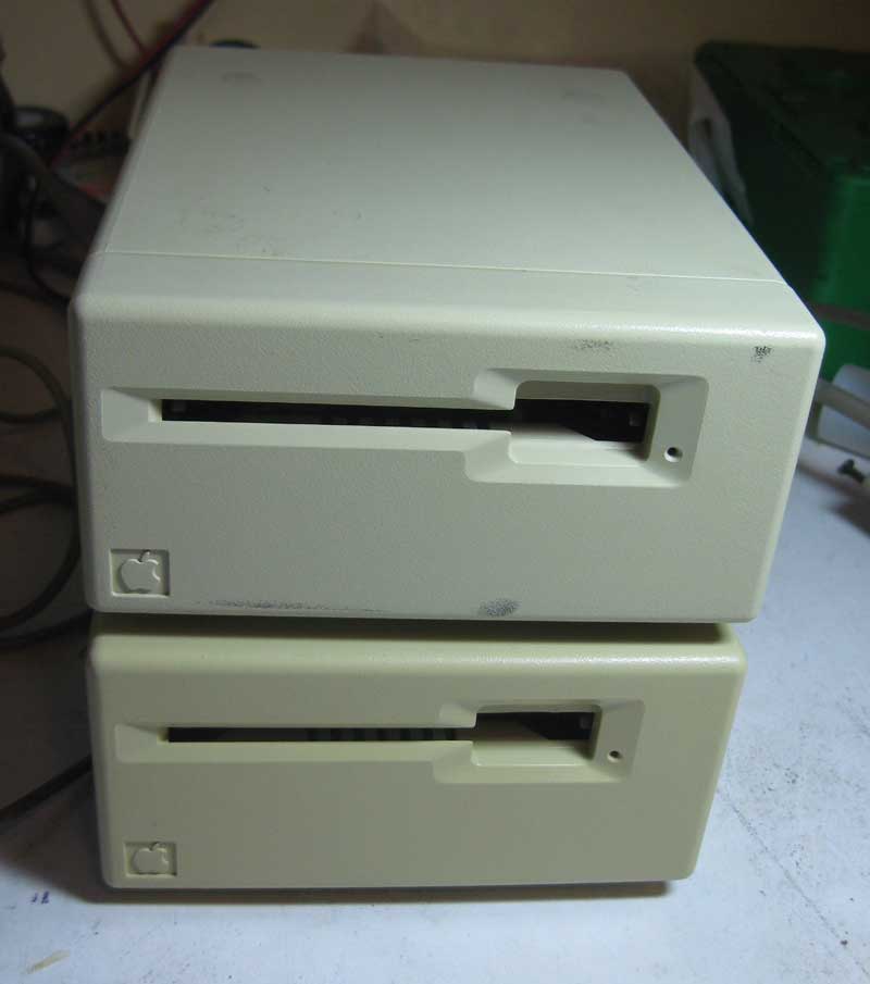
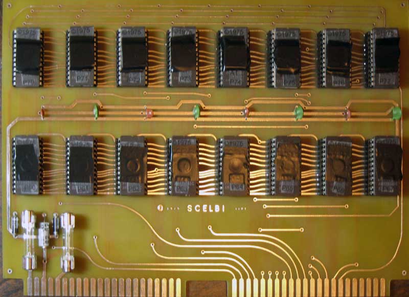
Mac 400K Floppy Drives
From my experience resurrecting the internal 400K drive, I knew that these units were very well built. I was thinking that I could probably get one of the two working. Maybe if I was lucky I could get both going and sell one to pay for my purchase.
When I received the units, I opened the box, only to discover that the units had been taken apart, and weren’t even completely reassembled. This concerned me a great deal, as I expected that when I found time to dig into them, that I would find that some inexperienced hacker turned a broken unit, into a broken beyond repair unit. I didn’t have time, to do any further analysis and the units were stacked at the rear of my workbench until time allowed me to dig into them.
Well, yesterday, I found that time. First thing I noticed is that all the screws holding the chassis and enclosure in place were gone, except for one. I pulled the first mechanism out of the chassis and took a look. The auto-eject mechanism was completely bound up.

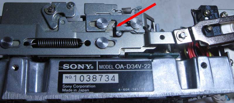
Mechanism Hang Up Point
Some of the components were bent, apparently from someone trying to force the mechanism open. One lever was actually completely frozen on it’s pivot. I disassembled the components that could be removed and cleaned off as much gunk as possible. It took a bit to free up the frozen lever, but it soon was operating smoothly. I straightened the bent components and checked the mechanism out. I noticed that sometimes a roller bearing would hang up partly through it’s movement, locking up the mechanism. I took a small file and filed a bit off of where it was hanging up, and the mech started working almost like new. With that problem, this unit might might have been misbehaving from the day it was made.
Now I reassembled the drive and attached it to my 128K Macintosh. The computer recognized the drive and it appeared to operate normally. I was able to format floppies and exchange them with the internal drive, so alignment and operation was perfectly fine.
I thought, maybe I’d be that lucky with the second drive and I put the first drive aside. Before doing anything else, I figured I would clean the mechanism of the second drive. It seemed to have much less wear then the first drive. I closely examined it and the mechanical pieces seem to be in excellent shape. After cleaning, lubing and reassembling, I hooked it up.
After turning it on, the stepper motor moved the head to the inside track and continued turning. This one had some kind of problem with the control system. I tried a lot of things, including swapping controller boards with the other drive with same result as before. I decided that it was pretty likely that the sensor that indexes the heads to the outer track probably was not working.
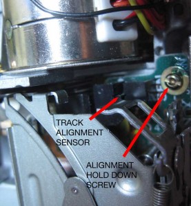
Track Alignment Sensor
After some more mucking around, I decided to do a search on the internet and came up with a “Click of Death” result that matched my problem. It seems that I was on the right track, and it was very likely that the head indexing sensor wasn’t working. I removed the mechanism again and used a sewing needle to try to clean the tiny slots in the sensor. The needle seemed to draw away some kind of oily residue from the slot. I kept at it until I didn’t see any more of the oily residue. I wonder if someone had sprayed something into the drive as part of a vain repair attempt.
I put the drive back together and I was in luck, as the “Click of Death” was gone and the drive seemed to boot normally. However I encountered a new problem. This drive’s alignment didn’t match my other drives or the old disks that I still had from back in the “old days”. This was clear, as floppies formatted and created on this drive would only boot and be read on this drive. Floppies created on other drives would not work in this drive.
This created a bit of a dilemma for me, as the factory seal on the alignment mechanism still was present. Either the factory alignment was off or somehow the problem with the sensor had affected alignment. I tried cleaning the sensor again to see if it would get better, but had no better luck. After much thought, I decided that I had no choice, but to muck with the factory alignment to try to make it better.
Normally you will align a floppy drive with special test software and a calibration disk and some test equipment. I have neither the software or a calibration disk, so I figured that I would just try to “wing it” by getting it to read disks made on my other drives. The alignment setup can be accessed with the unit completely assembled.

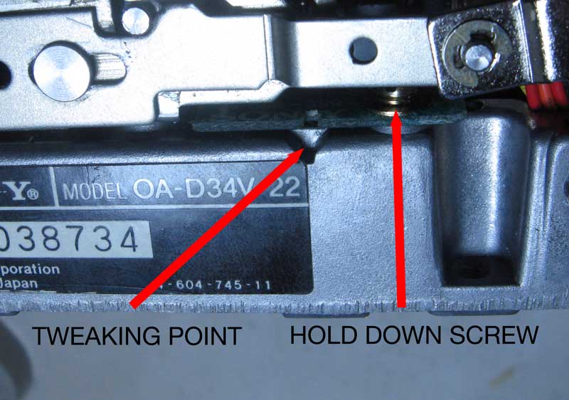
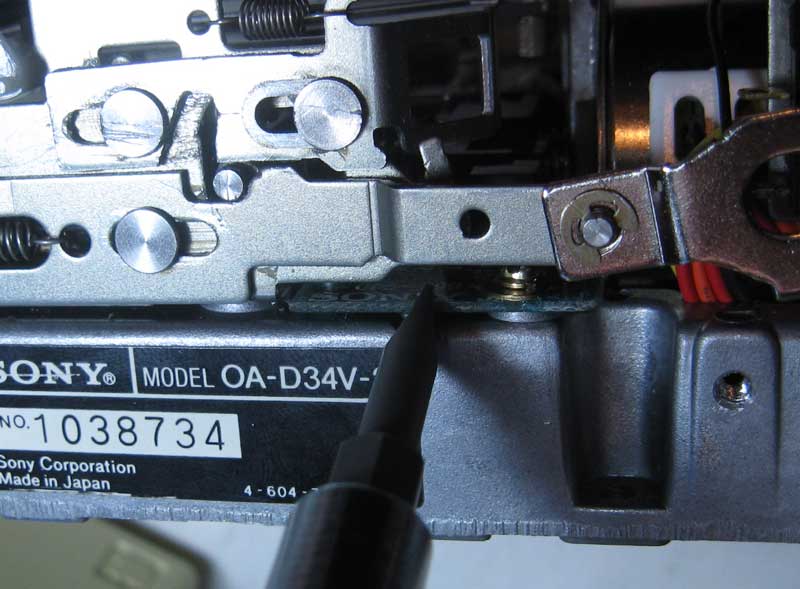
Floppy Alignment Points
You loosen the hold down screw just a bit, so that the board holding the optical sensor can be moved back and forth, but not so much that it is completely free. On the side of the chassis is a groove that matches a groove in the board. Using those grooves, you can use a flat bladed tool to tweak the board in very small increments.

Tweaking Alignment
After a lot of tweaking and testing and re-tweaking and re-testing, I have the second drive working as well as the first one. I wonder if this drive had problems with alignment from the factory, which is why the mechanism seems to have had so little use. I also continue to wonder if the problem with the index sensor had affected alignment. In any case, the drive functions well now, and floppies can be freely interchanged with my other drives.
Once I pick up some M3-.50 by 8 MM screws with matching star washers, I’ll be able to put both drives back together. I’ll probably sell the extra drive, as I just don’t see the need to keep a back-up parts drive.