First Pass of a Mantua General Repaint

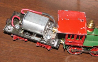
First see this old old blog post about the remotoring and change to the drawbar that I did a few years ago.

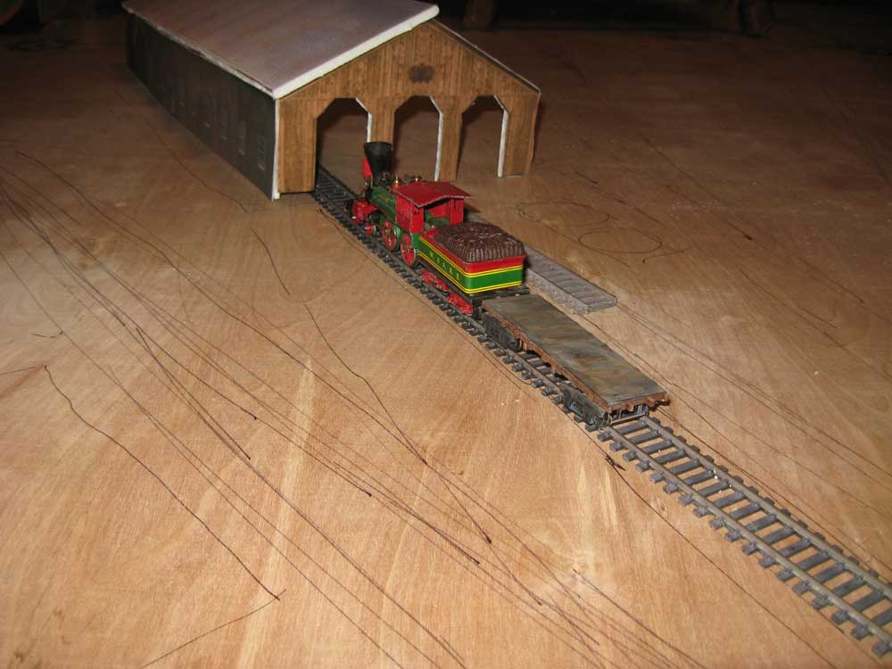
I am not a master modeler, but more recently, I’ve been working on changing an old Mantua General Locomotive over to the paint scheme of a US Military Railroad Norris type locomotive. With City Point being my main area of focus, I found some really good images of the Govener Nye, and decided to use that locomotive as my prototype.

The original paint job was severely chipped and probably not very great to start with. I stripped the old paint off with lacquer thinner and then repainted. Here is the result.

Generic USMRR Locomotive - paint based on Govenor Nye, a Norris built 4-4-0

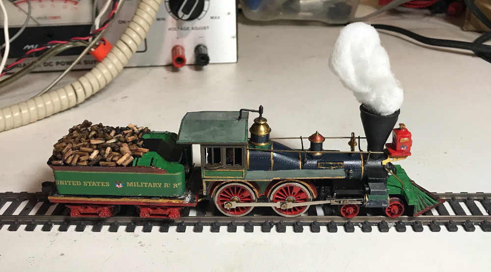
Generic USMRR Locomotive – paint based on Govenor Nye, a Norris built 4-4-0

I used an ancient can of Humrol #96 RAF blue that was left over from my days as a wargamer for the Russian iron, and am very pleased with the result. Other paints were from what I had on hand. I’m not all that happy with the green, but it will do for now. Decals are from Microscale’s Eastern USMRR set.

Besides the repaint here are some other things that I have done with this locomotive.

I added a DCC decoder using a Digitrax DZ-123 Z scale decoder, which can handle the 1 AMP motor. At this time, I don’t plan on adding sound to my Civil War locomotives, thinking that an external sound system will be more impressive. For example, I’m contemplating having an actual whistle that will be controlled with the DCC throttle, just like any other locomotive with a built in sound system.

I also added an engineer to the cab, but he is not very visable.

After mucking around for a bit trying to make the Matua supplied wood pile look more realistic, I ended up replacing the wood in the tender. I scored the sides of some round toothpicks with a fine tooth metal cutting sabre saw blade. Then I stained them and then cut them to size using a end cutting pliers. After positioning them losely on the tender, I used diluted elmers glue to attach them to the top of the tender.

What’s up next? I will add a line so the miniature engineer can ring the bell. I’m considering adding a working headlamp, but that may wait for a later date. I also need to program the speed tables for the DCC decoder. I will probably add a small magnet to the smoke/steam, so it can be removed when the locomotive is shut down, yet be a little more firmly attached when the locomotive is in motion.

Model Railroad Foundation/Benchwork

Here is my first attempt at building a benchwork foundation for the first section of the City Point layout. Main motivation is light weight while maintaining maximum rigidity in order to allow for portability. My last layout used an L-Girder design. While the L-Girder design was very suitable for a stationary layout, because of space considerations, I need to make this layout movable. A L-girder design would be hard to make portable.

Benchwork

Benchwork-Foundation

It is made of plywood underlayment. It is cut into 3 & 1/2″ strips and notched to interlock on 16″ intervals.

notch in plywood

notch in plywood

While it is light, I’m hoping that when fastened to the bottom of the plywood layout that it becomes rigid enough that I don’t have problems with damage to the track work and scenery during moves.

Engine House Mock Up

Using photoshopped, colorized images of the side, entrance and roof of the real engine house, I have created a HO scale mock up of 2 sides of the engine house and one side of the roof. Images were printed on matte paper on an inkjet printer and glued to foam core board. The engine house was actually 150 feet long by 50 feet wide – this is a true HO scale mock up, so its a little over 20 inches long and 7 inches wide. I will likely improve the look of the mock up in the future with a thinner roof made with cardboard or plastic instead of foam core and some detail parts and add the cupola that belongs on the roof. I have found that Grandt Line makes 6 over 6 windows that should made a nice upgrade over the printed windows. Any edges of the foam core that show will be painted over.

engine house mock up ii

engine house mock up ii

A front view gives a little better perspective of how the mock up looks next to a Mantua General.

engine house mock up with track plan

engine house mock up

Finally a view of this section of the layout with the rough track plan highlighted in yellow with photoshop. This gives an idea of the proportions of this part of the layout. The water tanks would be just to the side of the engine.

engine house mock up track plan

engine house mock up track plan

The open space towards the bottom of the image will contain a bit of the bluff that was on both sides of the cut that lead to the wharf. The next module to the right side will contain a piece the end of the trench line that protected City Point, as well as some crossovers on the incoming tracks.

Engine House colorization version 2

engine house side-version 2

engine house side-version 2

I hope that this is the final version, as I have other projects to pursue. Changes include coloring railroad trucks, the engine and most noticeably the wagon. I also slightly “weathered” the roof and tweaked things around the foliage. The color I’m least confident of, is the wagon box. I made it blue to match quartermaster wagon colors, but it’s just a wild guess. The red wagon and railroad wheels were very common at the time, so at least they are plausible.

Next thing I’m going to try to do is to build a model engine house with foam core board covered with printed (colorized) images of the actual engine house.

Colorized City Point Engine House Picture

Just learned how to colorize a black and white image with photoshop. It’s easier than I thought it would be. Though this image is just a hack job, it shows what it possible. It also can be used to help pick the colors in my actual model.

Colorized Engine House Picture

Colorized Engine House Picture

Let me know what you think of the color choices.

First Mantua General Remotoring Experience

Mantua Remotoring

Mantua Remotoring

I generally followed Al Muellers recommendations for replacing the drive line – though I did have difficulty drilling and soldering the music wire into the brass rod on the engine side. The tender side was easier, since I drilled the smaller hole and used it as a pilot hole for the motor shaft. This caused the drive wire to be lined up with the shaft, even if it wasn’t perfectly centered in the brass rod.

The shortened drawbar was cut out of scrap PCB material. The copper side is cut, so that there is no short circuit between the tender and the cab.

The other thing I changed was mounting the Nichibo PC-130 motor. I found I had a couple of screws that fit the mounting holes on the face of the motor. I presume that these are a metric size. I decided to use some scrap sheet metal to make a mount. It is bent at a 90 degree angle and using a #6 screw, mounted to the tender floor, opposite the hole that is used for feeding track power back to the tender. This provides a solid mount that, if necessary, can easily be removed or adjusted. I will eventually add DCC, but not sound, as I am looking at developing an external sound system, which will be able to produce far more dramatic effects that the small speaker in a tender could produce.

The Nichibo PC-130 motor produces incredibly improved low speed operation. I’m just amazed at the dramatic difference that this made. I haven’t yet calculated scale top speed using a traditional 12 volt power pack, but I’m guessing that it is way below capabilities of a real 4-4-0. Since I’m only modeling the yard and port, where speed would be low anyway, I’ll probably live with it.

I have some more things to do with the locomotive.

  • improve tender truck electrical pickup
  • replace front truck and tender wheels
  • address an issue with tractive effort, which seems inadequate at this point – perhaps more weight is all that is needed
  • add tender couplers – may use knuckle couplers initially in order to do some testing, but eventually I want to use link and pin
  • paint and detail as Liet. Gen Grant
  • Brass Bands at City Point

    During lunch hour today, I took the opportunity to visit the Addison Gallery of Art on the campus of Phillips Academy in Andover, Mass. The purpose of my visit was to see the original painting, “City Point, Headquarters of General Grant” by Edward Lamson Henry. The painting is currently in storage, but by arranging with them in advance, the curators were kind enough to bring it out for me to see.

    City Point by Edward Lamson Henry

    City Point by Edward Lamson Henry

    What a treat to see the painting in person. The painting is incredibly detailed and digital images do not do it justice. Here is a better image than what I was able to capture. View the zoomable image to see the amazing degree of detail in this painting. Among them, is a brass band, playing in front of Grant’s Headquarters. Brass Bands were a fixture at City Point, especially during the winter, when active campaigning was of questionable value, due to what the weather could do to the the Virginia road system.

    Brass Band at City Point

    Brass Band at City Point

    I expect that the figure sitting on the bench at the left side of this detail, is meant to represent Grant, himself. I think Mr Henry was trying to tell a story with this painting, much like some model railroaders do. I’ll try to make an effort to post some more images with details over the next few days.

    ambrotype studio at city point

    I just noticed in the corner of this picture of the turntable and engine house at City Point that there is an ambrotype studio.

    Turntable and Engine House

    Turntable and Engine House

    A high res version can be downloaded front the National Archives or from Wikipedia.

    A few observations. The wagon isn’t a typical military wagon, so I suspect it might be a support wagon for the photographer. The Ambrotype sign written on the side of the railroad machine shop on the left side of the image also is a bit puzzling. I doubt that the army would allow a private photographer to advertise on the side of their building. The most likely explanation that I can think of, is that this is actually A.J. Russel’s studio, as he was an army captain tasked with documenting by photograph, the US Military Railroad during the Civil War.

    Here is a crop of just the Studio. Notice the north facing open roof. Before the advent of high intensity lighting and flashes, photography studios typically would have large north facing windows to indirectly light the scene. Looks like that in this case, they just opened up the roof.

    Ambrotype Studio at City Point

    Ambrotype Studio at City Point

    The remaining question, which I can’t answer, is whether Russell was also doing some freelance work while at City Point.

    Modelling a Time and Place: My Proposed Model Railroad

    Most model railroaders eventually work towards modelling a certain date and time. In some cases, the plan is to tell a bit of a story. I guess I’m moving towards the extreme end of things in my City Point model railroad planning.

    I was originaly thinking of modeling early December, 1864, when the Sixth Corp infantry returned from the Shennandoah Valley through City Point. This was to provide a viable reason to model a significant number of infantry using the port facilities.

    However, after some recent digging, I think I have come up with a much more interesting timeframe.

    In March there was heightened quartermaster activities related to preparations for a major campaign. On March 27th and March 28th, 1865, a lot was also going on at Army Headquarters.
    President Lincoln and family was in port aboard the River Queen, taking almost daily trips to see points of interest.
    Sherman arrived late in the afternoon of the 27th, leaving around noon on the 28th aboard the Bat, a captured blockade runner.
    Sheridan arrived late at night of the 27th.
    Admiral Porter was also present.
    There were several meetings among these men during the late afternoon and evening of the 27th and also the next morning.

    Up through the 28th, the 114th Pennsylvannia Zouves were on provost duty at City Point. The 114th Pennsylvannia had one of the best bands in the Army of the Potomac and it was known to serenade General Grant several times a week while on provost duty. They were still uniformed in Zouve attire, even at this late date in the war.

    Also…
    Several thousand prisoners were captured at Fort Stedman on the 25th – I don’t yet have information on transportation dates, but they were almost certainly shipped to prisoner of war camps through City Point, shortly after that battle.

    Newly recruited units were arriving in this general timeframe to reinforce the armies for the upcoming spring campaign. Because of the great need for troops during this period of the war, the Union armies didn’t wait for new regiments to completely get recruited, but would often send incomplete regiments to the front, following later on with remaining companies. An example of this is the 18th New Hampshire, which had 6 companies sent to City Point in September, followed later on by individual companies, as they were recruited. At first, the regiment was attached to the engineer brigade and helped build the City Point defenses. Later on, they did some service in the trenches. Company H arrived at City Point on March 30th. Company H was given weapons and rudimentary training on the 31st and joined the regiment in a firefight in the front lines the very next day. On April 3rd the 18th New Hampshire joined the army as they occupied the vacated Confederate trenches. They also participated in the pursuit of Lee’s army.

    Sounds like a fascinating time and place to model, what do you all think?

    regards,
    Mike W.