Woz’s take on the Apple 1’s noisy -5 volt supply

There was a recent thread about the Apple 1’s noisy -5 volt supply on Applefritter, so I asked Woz the following:

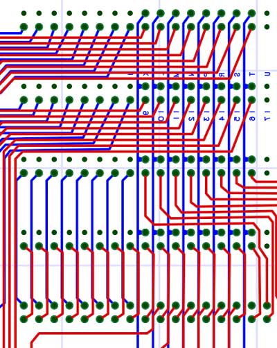
One thing a number of us have noticed while working with reproductions of the Apple 1, is the amount of noise that exists on the -5 volt supply. The stabiliy of the -5 volt rail appears to be affected by the edges of the -12 volt clock that is used to control the video shift registers. Usually it’s not a problem, but I’ve run across a few cases where it affected DRAM reliability. Adding additional decoupling to -5 near the shift registers and the -5 regulator seems to clean things up considerably.

I was wondering if any of you remember noticing that noise on the -5 volt supply and if that ever was an issue back “in the day”.

I recieved the following reply from Woz:

I am sure that what you describe is valid, although I personally wasn’t aware of it.

I did the prototype of the Apple I and debugged the PC board version but didn’t look into such aspects. I’m sure you are quite correct. We knew that this was a low volume product since we were demonstrating the Apple II before shipping the first Apple I. Hence, we did not have many to become aware of issues like this. Part of the problem was that my time was being spent on the Apple II completion.

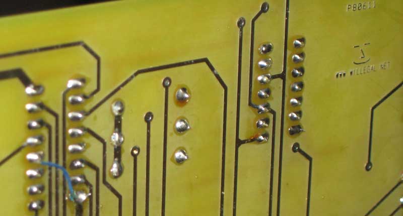
The ‘productizing’ of the Apple I came under Steve Jobs. I always optimized my prototypes for short distance wiring, but the PC board introduced longer power traces. Please forgive me. I never looked closely at this aspect. I certainly over-minimized in bypassing decoupling capacitors throughout the chips and RAM. I did worse too that was probably copied over to the PC board, like not having pullup resistors on unused TTL inputs. Still, had we at Apple been aware of such an issue while selling maybe 150 Apple I’s, we could and would easily and quickly have rectified it. But we didn’t test fully a product that was a temporary place-holder before the big product. We did try to buy back every Apple I in exchange for Apple II’s.

We had more luck than anyone deserves with things working out just enough to suffice and do what we did.

I will tell you that I and others did observe the power lines and did not notice noise or spiking. And, as I said, it was never a problem that was called to our attention, or at least to my attention. We could have put out an errata sheet for owners to fix the problem themselves, since this was very much a maker product (local stores could modify things to use 16K RAM’s, for example, and they did.

I am totally interested in hearing such things even after all these decades. I awoke one night in Quito, Ecuador, this year and came up with a way to save a chip or two from the Apple II, and a trivial way to have the 2 grays of the Apple II be different (light gray and dark gray) but it’s 38 years too late. It did give me a good smile, since I know how hard it is to improve on that design.

best,
Woz

Marconi 2018A Signal Generator

Marconi 2018A

Marconi 2018A

I recently picked this up off of eBay for less than $200, including the cost of shipping. Though ebay is a crap shoot, this time, I think I scored. It seems to work perfectly with the frequency and power output exactly matching my Kenwood TS-530S. The seller listed it as having an intermittent keyboard problem. I haven’t see any sign of that, but did notice in the manual that if reverse power exceeds a certain level that it will lock up the keyboard until power cycled. I’m guessing that this is what happened to the previous owner. There is a calibration sticker on the front that says “CALIBRATION LMITED to Residual FM <10Hz 01-16-2013 TECH 057", so it seems that it had some sort of calibration, just last year. This unit has seem a lot of use, as the lettering on some of the keys has worn off, but I can live with that. The manual for this device lists a copyright date of 1984, so the design has been around a while. The METRICTEST.COM website says that the manufacturer list price in the US was $5,995 for the 2018. Here is a little more about the specifications of this device.

Performance Characteristics:
Minimum Frequency: 80 kHz
Maximum Frequency: 520 MHz
Frequency Resolution: 10 Hz
Time base stability: 0.1 /mo
Minimum Output Power: -127 dBm
Maximum Output Power: 13 dBm
Power Resolution: 0.1 dB
Output Accuracy: 1 dB
Output Impedance: 50
Ohm Maximum Single-Side-Band Noise: -130 dBc/Hz
Harmonics (noise): -30 dBc
Non-harmonics (noise): -60 dBc
Modulation: AM, FM, Phase

What am I going to do with this unit? Well besides confirming that my Kenwood TS-530S is in tune, I’ll also be able to test out the HAL ST-6 and use it to develop the software I need to successfully receive RTTY messages with my vintage computers.

What is SCELBI’s MEA

Like so many other things in the SCELBI world, it’s best to let the creators describe it for you.

THE SCELBI MONITOR/EDITOR/ASSEMBLER PROGRAM, ABBREVIATED IN THIS MANUAL AS “MEA” IS A POWERFUL SOFTWARE PACKAGE THAT COMBINES THE FUNCTIONS OF A MONITOR, EDITOR, AND ASSEMBLER IN A RESIDENT, CONVERSATIONAL TYPE ARRANGEMENT. THE PACKAGE IS STANDARDLY SUPPLIED ON A PROGRAMMABLE READ ONLY MEMORY ELEMENTS THAT RESIDE ON PAGES 60 THROUGH 77 (OCATL) FOR USE IN A SELBI-8B MINICOMPUTER. I/O ROUTINES FOR THE PACKAGE ARE SUPPLIED ON TWO SEPARATE “PROMS.” THE STANDARD SCELBI AUDIO TAPE DRIVING PROGRAM RESIDES ON PAGE 77. I/O ROUTINES FOR THE SPECIFIC I/O HARDWARE TO BE USED WITH THE SYSTEM IS PROVIDED ON A PROM ON PAGE 76. TWO STANDARD I/O VERSIONS ARE AVAILABLE. ONE FOR SYSTEMS EQUIPPED WITH THE SCELBI OSCILLOSCOPE ALPHANUMERIC DISPLAY INTERFACE AND SCELBI ASCII KEYBOARD INTERFACE, THE OTHER FOR SYSTEMS USING A MODEL 33 TELETYPE INTERFACED WITH THE SCELBI BIT-SERIAL TTY INTERFACE. OTHER TYPES OF I/O DEVICES CAN BE ACCOMMODATED BY SPECIAL ARRANGEMENT AND SUBSTITUTION OF APPROPRIATE I/O ROUTINES PROGRAMMED ONTO A PROM ON PAGE 76.

Here is the cover of the manual, which can be found at scelbi.com.

SEA cover page

SEA cover page

This development environment, which was available in 1975, was quite an achievement for the time. The environment was “robust” enough that Mark Arnold used it to develop SCELBAL. Few other “personal” computer systems available in 1975 had such capabilities built in. For instance, Microsoft BASIC for the 8080/Altair was developed in emulation on a PDP-10.

Also at scelbi.com is a intel hex file of the contents of the PROM card. This version of the contents was painstakingly reconstructed by Mark Arnold from an object listing that was sent from Nat Wadsworth to Mark when Mark started experiencing problems with the EPROMs on his system back in the old days. It’s very fortunate that Mark saved this listing.

Start of MEA Listing

Start of MEA Listing

The listing was just a raw dump and where it was folded the data was illegible. Mark and Cameron Cooper managed to get MEA up and running in emulation and used the emulator to help reconstruct the missing data, so they believe the hex file at scelbi.com is correct.

MEA listing with missing line

MEA listing with missing line

The version they have, is set up for the TTY interface. So far, we haven’t been able to find a surviving version of the oscilloscope drivers that would replace the TTY drivers on page 76. I think it’s rather unlikely at this point that we will be able to find the oscilloscope version, so that version will most likely have to be rewritten from scratch.

We have the TTY version of the MEA program and I have already done the TTY interface card, so we are getting close to having reconstructed a complete SCELBI 8B running MEA. After completing the PROM card, my next efforts will be to do the cassette interface, which will allow running the MEA system as it was intended on real hardware.

In order to get MEA working in my OS/X emulator, I’ll need to enhance the terminal support to act more like a real TTY as CR and LF are separate functions and I’ll also need to figure out how to support backspace. I also intend to add cassette interface emulation support to my emulator to allow complete support of MEA in emulation.

New Toy

Kenwood TS-530S

Kenwood TS-530S

This is another new toy of mine. It is a early 80s vintage HF transceiver that will be used as critical piece of the new aspect of my Vintage Electronics Hobby that was previewed by a post showing another device. This Kenwood TS-530S was purchased as working with new tubes. Like many things on ebay, the reality of the condition wasn’t quite up to advertisement. First power up revealed an issue with intermittent operation. Investigation on the web shows that there are frequent problems with the band switch with these units. I found a couple of tutorials online and preceded to tear it apart.

Band Switch

Band Switch

Though I was a bit intimidated at first by the number of discrete components, the more I worked on pulling this device apart, the less concerned and more intrigued I became. The red arrows show the 7 boards that contain wipers and contacts that are rotated by the bandswitch. I pulled each of them out and checked for connectivity in each position. I found a couple of the wipers were not making any contact at all. I also smelled what I thought probably was tuner cleaner, so someone probably already tried to rectify the issue by cleaning contacts, but based on what I found, that approach had no chance of success. I corrected all the issues that I found and re-installed everything and now it appears the bandswitch probably is working correctly. One thing I did in addition to the normal instructions was measure each of the spacers with a dial micrometer so I was sure I could replace them correctly, should I accidentally mix them up. In case someone else has an issue on a TS-530S, the measurements of each spacer, starting from the front are .1″, .6″, .6″, .2″, .25″, .5″, .35″, .2″, .25″, .15″, .2″, .2″. I was a bit surprised that the measurements of this Japanese made device were in thousands of an inch, but maybe that is because PCB layouts are frequently done in that measurement system.

I’m not 100% sure that all is well. I haven’t done any transmitting and I decided I need to align/recalibrate the entire transceiver before declaring success and moving on. I have most of what I need to do this, but I do need to build a dummy antenna load and find a signal generator. Oh boy, an excuse for more gear. Stay tuned for new adventures in this new aspect of my vintage electronics hobby.

73s
KC1CKV

Posted in HAM

Reproduction SCELBI 8B now running SCELBAL

This has been a very long time coming and I’m super excited to see it finally running.

Here is a very poor quality video of it in action.

Note that the versions of SCELBAL found on the net require 12K because they include all the available features and options. In order to run in a 8K system, the array feature is going to have to stripped out.

A SCELBI 8H-B

I’m calling a SCELBI 8H that includes a 4K memory card from a SCELBI 8B a SCELBI 8H-B. See the original 8H-B here.

Attaching a single 4K memory card to an 8H is easily done because of the way that SCELBI memory cards are addressed. While reading the following description, keep in mind that on a SCELBI, a bank of memory is considered 256 bytes.

On a SCELBI 8h, there are 4 bank select lines connected to each slot for a total of 16 bank select lines. This provides addressing for 4 banks or 1K per slot and 16 banks or 4K for the entire system. The are 4 bank select lines connected to each of the 4 slots at different points as can be seen in this image of part of the 8H backplane.

8H backplane bank selects

8H backplane bank selects

On a SCELBI 8H 1K memory card, each of the four banks available on the 1k card, is connected to the backplane at four different points. In the picture below, the line for the first memory bank on that card is highlighted in green.

1KSRAM 1st bank select

1KSRAM 1st bank select

Depending upon which slot the card is plugged into, it will pick up the 4 bank selects for that slot, thus automatically providing a different address range for each slot, without requiring extra decoding logic on a memory card.

The SCELBI 8B memory design is a little different in that the memory expansion card decodes 16 banks for each slot (4k) and a total of 64 banks (16K) for the entire system. This image shows the 64 bank select lines going to the 4 memory slots on a SCELBI 8B backplane.

8B memory selection

8B memory selection

The 4K memory card is also different, with the 16 bank lines all feeding into the on board circuitry separately.

4K memory selects

4K memory selects

This design also requires extra complexity on the memory card. The 16 bank selects on the back plane must be demultiplexed into 4 chips selects, each of which selects one of the four rows of memory chips.

So how do you connect a 4K SCELBI memory card to the 8H? A few of you may have already deduced how to do this. You simply jumper all 16 banks selects available on a 8H backplane to a single slot, making sure you leave the other slots empty. This still leaves you a 4K system memory capacity, but will significantly reduce the cost of creating a 4K SCELBI 8H.

The SCELBI 8B memory addressing architecture is unique in my experience. I think it was deliberately designed to allow use of a single 4K memory modules in a SCELBI-8H. Perhaps Nat and Bob were considering a cost reduced 5 slot SCELBI 8H backplane that would take advantage of this architecture.

SCELBI 8B Early Adopter PCB Sale

I am now offering 8B PCB set to early adopters a special price of $275 plus shipping. Though my prototype system has been brought up and basically checked, it hasn’t been fully checked with a full complement of memory and PROM cards. Also I/O port testing has been minimal. There could be additional issues beyond those already documented in my blog that will require rework. Once checkout is considered fully complete, the price of a board set (minus PROM card) will rise.

The introductory set contains one each of the following PCBs. Extra SRAM cards are available now at $50 each. This set does not include the PROM card, which is still under development. Estimated time before PROM card will be available is 3 months, give or take 2 or 3 months.

1100 CPU
1101 DBB
1102 INPUT
1104 Front panel
1106 memory expansion
1107 4k SRAM (1)
1108 8B Backplane

Send an email with your address and and questions to:mike@willegal.net for a shipping quote and ordering information.

I’m not sure when chassis sheet metal will be available, as I’m looking for bargain on a used Box and Pan Brake, so I can fabricate them at substantial savings over contractors prices. Note that not just any brake will do, it has to handle a minimum of 2′ of 16 gauge stock with at least a 4″ depth. for now, you can fabricate your own temporary chassis or use an off the shelf Bud AC-413. The only problem with the Bud chassis is that the original chassis were 3.5″ high and the AC-413 is only 3″ high.

My Improved Understanding of the SCELBI Data Display

During my debug of the 8B, over the last couple of days, I improved my understanding of the data display on the SCELBI front panel. Though it is clear from the block diagram, some things just don’t sink into my brain without some additional lessons, usually learned the hard way.

The data display simply shows the contents of the memory location that is currently being addressed. I already knew that when you stop or step the SCELBI, it stops after setting up the address bus, but before executing the next cycle. In 8008 terms, this is at CPU state T1. The two status bits on the front panel are simply the two high bits of the high byte of the address byte. These two bits are not actually address bits, but known as the cycle control decodes, which is why the 8008 only has 16K of address space and not 64K. Another fact to consider is that both 1101 and 2102 memory chips have different input and output data lines.

The interesting thing that is a result of these design decisions, is that you can do simple memory tests from the front panel by writing a memory location, without even reading it. The data you write should show up on the front panel, without the need to even execute a read instruction. If you have a write failure, you will immediately see that the data you thought that you wrote is being displayed incorrectly and therefore has been written to memory incorrectly.

One other thing, without memory in the system, the data display will always show up as all ones. You can still jam instructions into the CPU, but you will not be able to use the data display as an aide to troubleshooting.

8B Running Tiny SCELBAL!!

I need to build another memory board before I will be able to run the floating point version of SCELBAL. I think I have most all of the parts on hand for at least 1 more board, so this shouldn’t take too long.

I had to debug two problems. First was a missing trace on the memory expansion board. This ran under the 7442 located at Z9 from pin 12 to ground. During design checks I check every pin on every chip for a connection to the correct net, but I missed the ground connection on this pin. The trace is completely obscured by the IC, so it’s invisible in images. It is documented in schematics and I probably should have caught it during design checking. Anyway, it’s not serious enough to qualify for a respin of the board, since it can be fixed by running a ground wire under the chip from pin 12 to pin 8 before soldering it (or the socket for it if you decide to use sockets) to the board. This fix will be practucally invisible to anyone inspecting the board.

Missing Ground Trace

Missing Ground Trace

The other issue was a pin bent under a memory chip. This took longer than the missing trace, as I was assuming that something was wrong with the soldering or layout on one of the boards.

2102 with Bent Under Leg

2102 with Bent Under Leg

I have done some rudimentary checkout of all the memory slots (with my 1 board) and so far they all look functional. The last slot was only half checked out, due to the lack of another 7442, which I haven’t gotten yet. I will not feel like that the system will be fully checked out until I get 3 memory plus prom board all working together. However, I’m confident enough that it will be ok, that for those of you that want to start building a SCELBI 8B, I’ll start a discounted early adopters program in the next couple of days.