It is well known among Civil War historians, that some states allowed soldiers to cast votes from the field in the election of 1864. These were California, Kansas, Kentucky, Maine, Michigan, Rhode Island, and Wisconsin. When possible, soldiers from other states, might be sent home to vote. In fact, Lincoln sent a letter to Sherman dated September 19th, 1864, asking if he could safely send Indiana soldiers home to vote in the election which was scheduled for the 11th October. Indiana was a particularly important state to Lincoln because of the large number of southern sympathizers in the southern part of that state.
What I haven’t seen mention of, is how the many civilian contractors supporting the efforts of the army dealt with the same issue. I found this note in the National Archives which gives a little hint of what had to be a difficult issue.
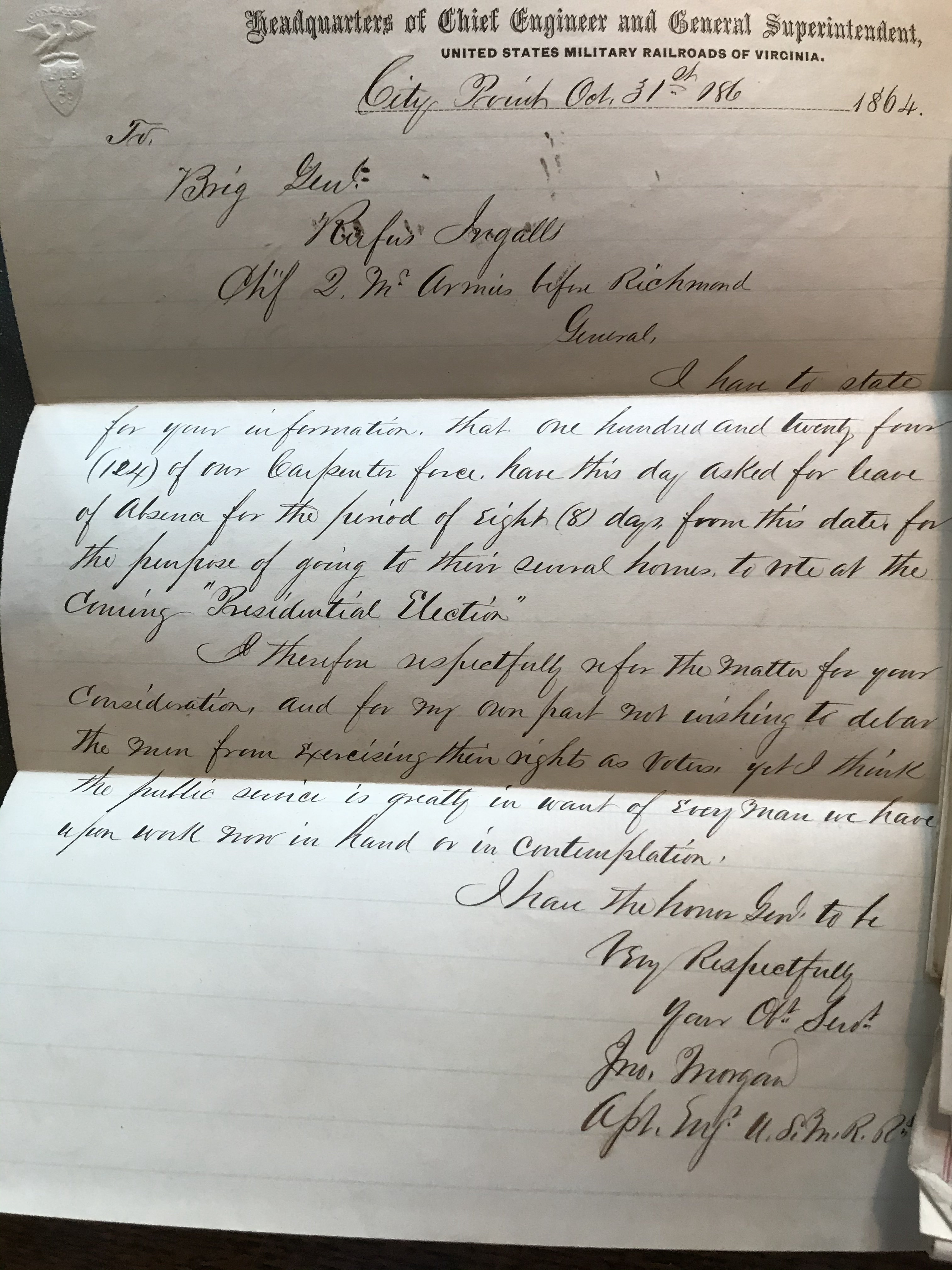
October 31st, 1864
To Brig. Genl Rufus Ingalls
Chief Q.M. Armies Before Richmond
General,
I have to state for your information that one hundred and twenty four (124) of our carpenter force have this day asked for leave of absence for the period of eight (8) days for this date for the purpose of going to their several homes to vote at the coming “Presidential Election”.
I therefor respectfully refer the matter for your consideration and for my own part not wishing to detain the men from exercising their rights as voters yet I think the public service is greatly in want of every man we have upon work now in hand or in contemplation.
I have the honor Genl. to be very respectfully your Ob. Ser.
J__ Morgan
___ Eng. U.S.M.RR.
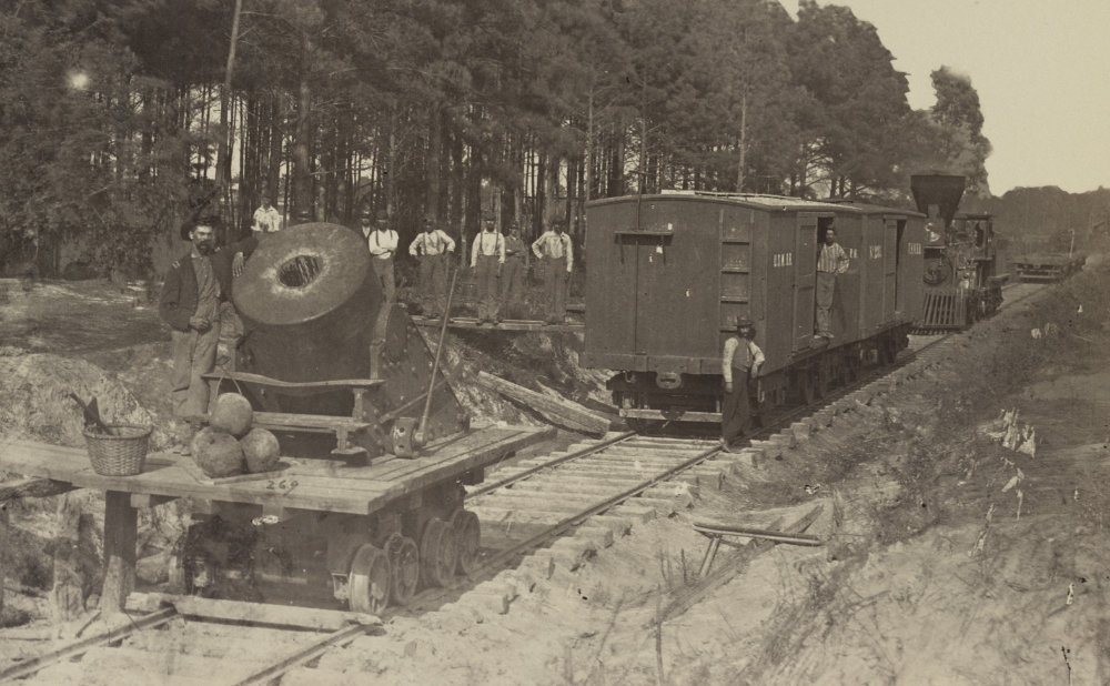
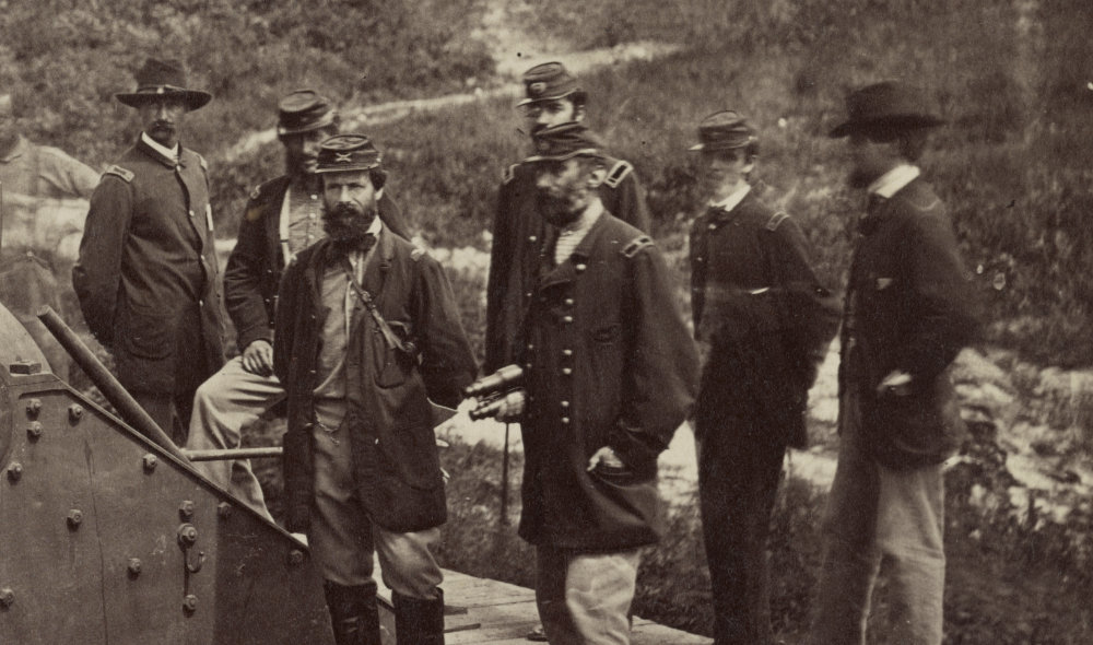
You should know that the fall of 1864, was a period when a large amount of construction was going on at City Point. Grant had realized that he wasn’t likely to break through to Petersburg until the next year’s campaigning season and the armies were preparing to settle in for a siege that would most likely last through the winter.
Like so many things in the archives, you only find one part of an exchange, which results in a little mystery. I don’t know exactly who Morgan was. A number of similar messages I’ve found related to the USMRR at City Point are from C. L. McAlpine, who was an engineer in charge of repairs. Perhaps more significantly, I’m also unsure about how General Ingalls responded to this message.
![Apple ][ replica poster](http://www.willegal.net/blog/wp-content/uploads/2021/02/apple-add.gif)