As look back at some of the blog postings I made during the early days of the Mimeo project, the excitement I felt, could be easily discerned. For better or worse, after nearly 7 years, that excitement is no longer there, and it’s time to move the project over to someone who has a strong passion for that landmark system.
I’ve transitioned Mimeo 1 sales to Corey Cohen. I’m sure he will do a great job selling and supporting people interested in building reproduction Apple 1 Computers.
Since first making them available in March of 2010, I’ve sold 167 Mimeo PCBs, the first few as part of a kit, even a few that were completely assembled and tested. I have greatly enjoyed the entire process from creating the PCBs in the first place, to fixing a few boards that customers needed help with. Especially gratifying, has been the great relationship that I have established with all the people that I have made contact with over the years. One thing that I never expected, when starting this project, was the amazing contacts I made with so many people associated with Apple during those early years.
However, the learning part of the process, which is one of things that keeps me interested in my hobbies, has not been there over the past few years. It is time to move the sales over to Corey, who has unbelievable enthusiasm and knowledge for and about those milestone computers.
SCELBI PCBS
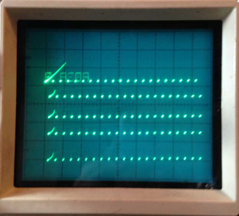
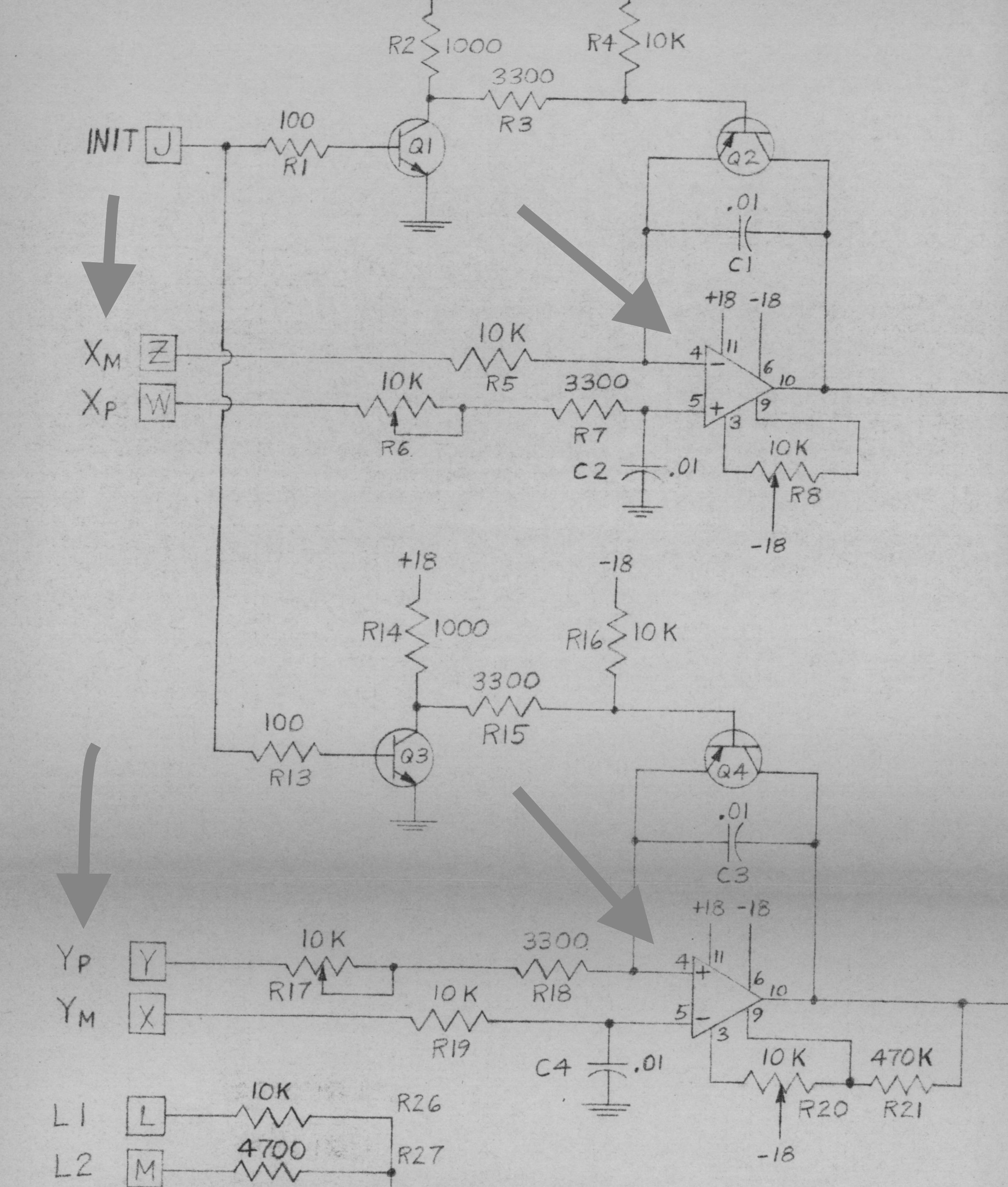
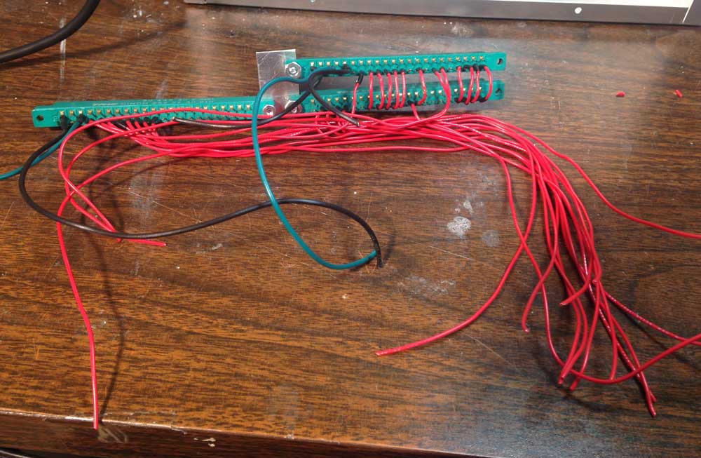
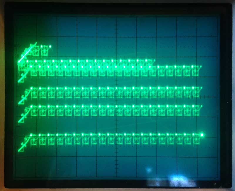
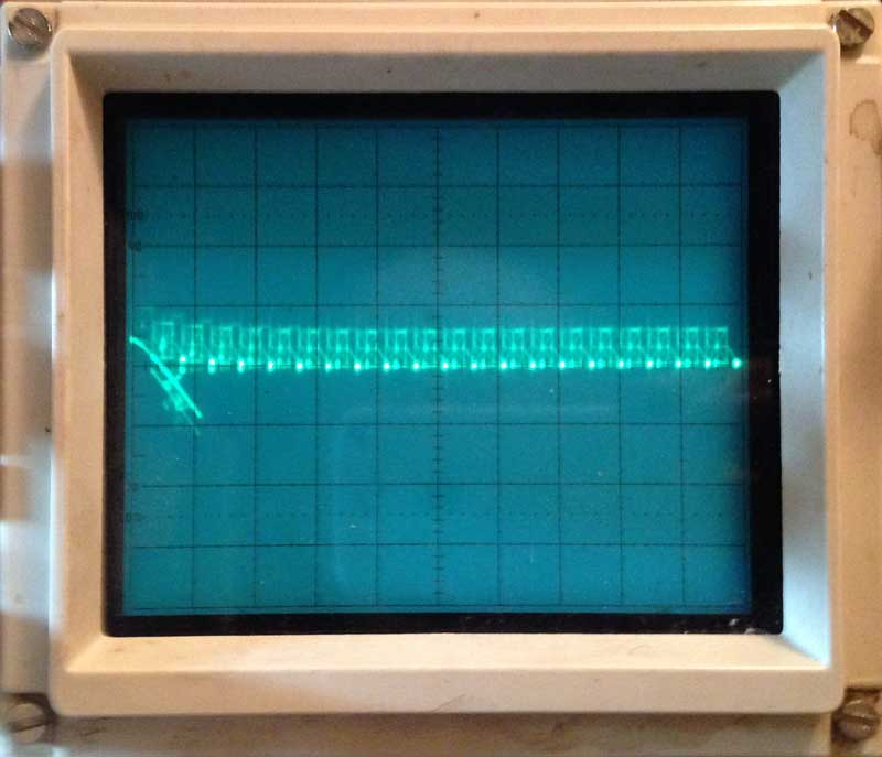
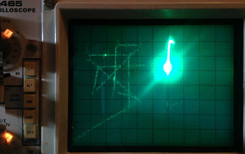
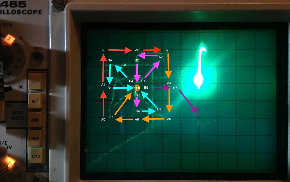
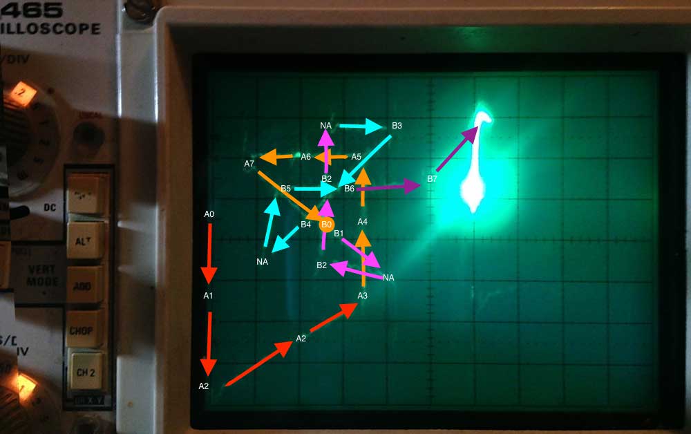
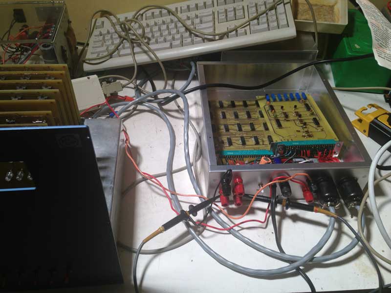
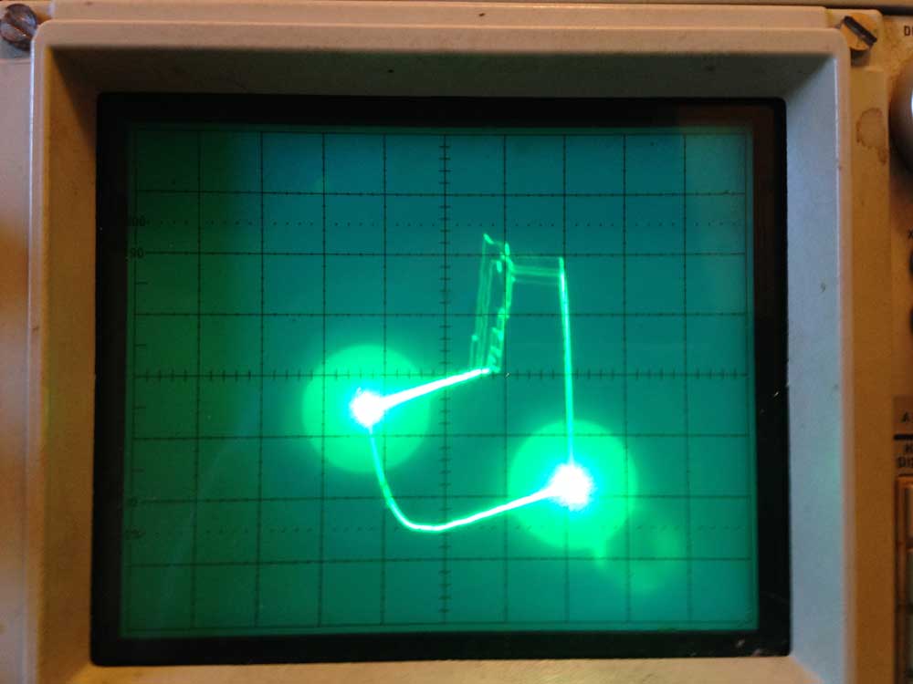
I will continue to sell SCELBI PCBs, as I am still excited about working on that system and learning a lot, while doing it. Blog followers will know that the Oscilloscope Interface PCBs, the last SCELBI boards that need to be reproduced, will soon become available to interested parties. I have some ideas for some even more obscure reproduction vintage computer projects. However, the Oscilloscope interface must be completed, before I move on to those projects.
Other Products
Other products I have sold in the past, will only be continue to be sold if I have remaining inventory in stock.
I presently have stock of the following
Brain Boards
Swift Cards
I am sold out of the following:
Apple II, rev 0 boards
SuperProto boards
PS/2 keyboard adapters.
Datanetics Keyboard PCB
The PS/2 Keyboard Adapter
The PS/2 keyboard adapter is a little bit of a special item to me. When I had those PCBs made, because of economies of scale, I had 150 fabricated. I never thought I’d sell all of them. In the end, I sold over 140 those little dongles, using the others for a number of my own special projects. Though they probably exist, I have never heard of a PS/2 keyboard that it didn’t work with. It was designed to operate with Apple 1 and Apple II computers. As I originally hoped, people adapted the design to a number of systems beyond that. The firmware has had minor firmware features and improvements made over the years, but the basic design hasn’t changed over all these years.
There have been a number of other PS/2 keyboard to parallel ASCII keyboard adapters designed over the years, some coming before, and inspiring my adapter. Though it could certainly be improved further, I sincerely believe my version is currently the best of the breed.
When I get the time to add them to my web site, I will be releasing to the public domain, with no restrictions, all design files, including firmware and PCB CAD files. You will be able to do what you want with it, make copies for sale, improve it, or just study the design for your own purposes.