My previous posts describe a little of the repair history of my Tektronix 465 and events leading up to this blog entry. At this point, after a repair of the trigger “A” control, the scope now would not display a proper trace. If brightness was turned up all the way, it would display only a tiny dot at the center of the screen.
Now I had to debug a new problem. Since the scope was in a useless state, there was no question about stepping up to the plate and moving into full debug mode. First thing I did was do some web searches to locate and downloaded the service manual.
An important early step in debugging sessions of this sort is to check system voltages. According to the service manual, the voltage test points are on the bottom board. With the unit on it’s side I checked the voltages and found that the -8 volt rail was near ground which was a big problem. Next step was to check the power supply electronics. After at least an hour or two of probing components and reviewing the schematics, I couldn’t find any obvious issue with the -8 volt power supply. Something else must be holding the -8 rail to or near ground.
The service manual gives some suggestions for isolating the -8 rail from horizontal amplifier circuit or the CRT circuit by lifting legs on some components. Since the CRT seemed fine, but the horizontal amp definitely wasn’t working, I started by isolating the horizontal amp. It turns out that there is a jumper designed for this purpose. I started by lifting one one leg of the jumper and sure enough, -8 volts returned to it’s proper value. So this must have meant that the problem with -8 volts was with the horizontal amplifier.
Most of the horizontal amplifier is on the bottom board, the same board as the power supply. I just needed to shift my probing to a different corner of the board. Since there was no obvious burn or failed component in that section, I started probing to find a defective component. My probing involved looking for a capacitor, resistor, diode or transistor that wasn’t operating correctly. Capacitors are checked for value and shorts. Diodes and transistors are checked with the diode test function of my DMM. Resistors are checked for value. The main complication is that the components are in circuit, and other components in the circuit can affect readings. After several hours of probing components and checking things while powered on I could find nothing that would indicate a problem that would short -8 volts to ground.
At this point, I went back to my original thought that spilt coffee might have worked it’s way into the system and caused some problem, like it did with the trigger control. Moving deeping into the horizontal timing system looked like a daunting task, but I figured that I needed to proceed. After all, a broken scope was no good to me.
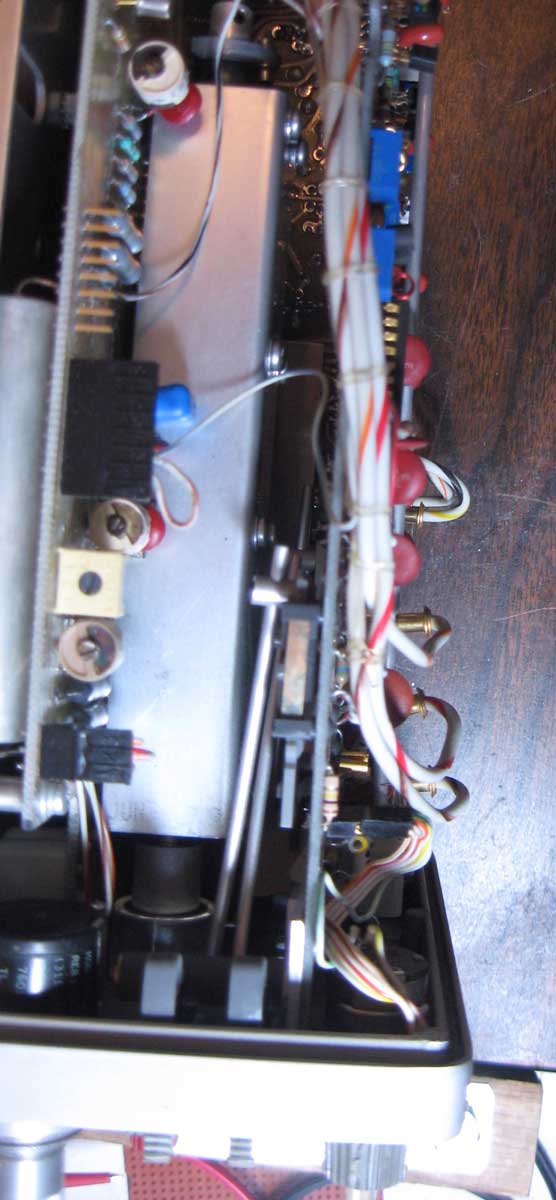
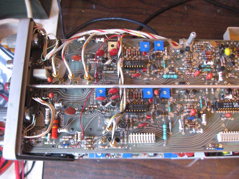
465 top view – horizontal control
Top view of trigger and timebase boards. Note the writing harness and individual wires that must be disconnected to remove these boards.
The service manual has a section that describes the steps to remove the trigger and timebase boards. There are wires that need to be disconnected or unsoldered to do this. At this point, I got out a digital camera and took some pictures of wiring that I thought I might forget how to reconnect. Some of pictures used in this blog were taken at that time. I also made some handwritten notes showing how the wiring needed to be reconnected.
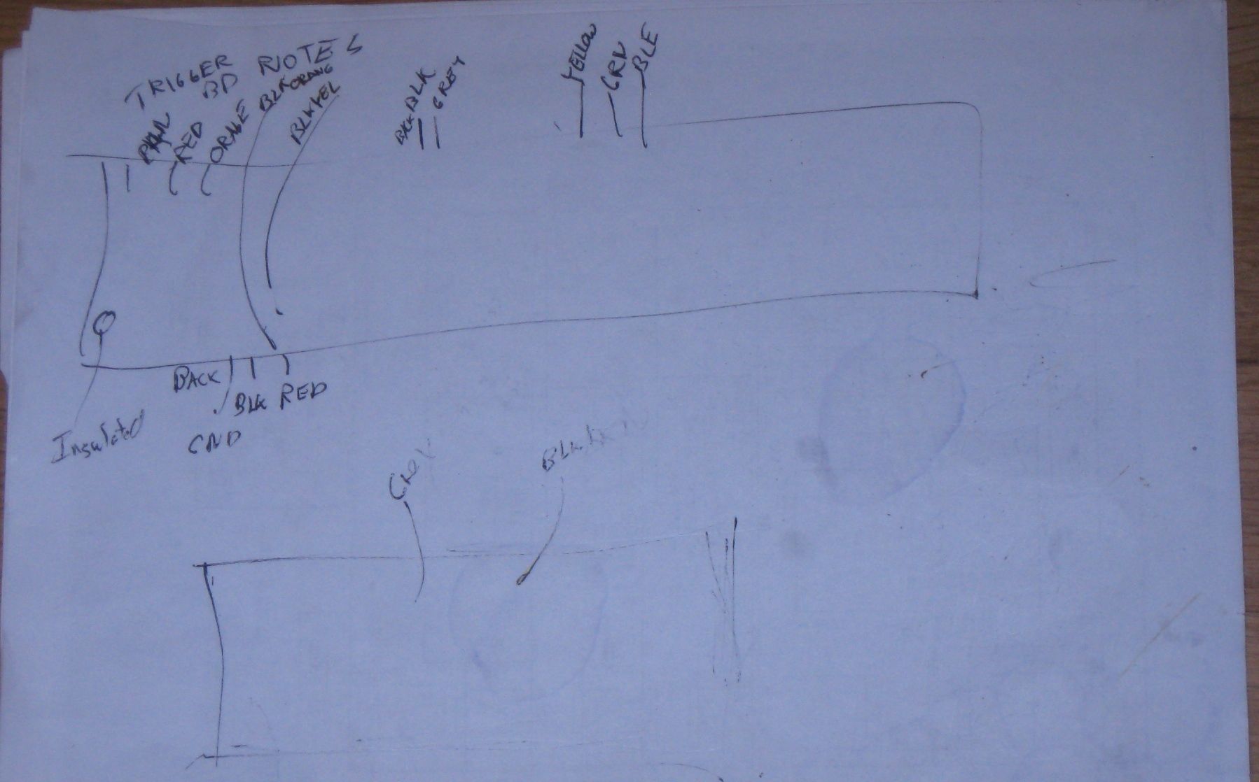
465 Wiring Notes
Following the instructions in the service manual as best I could, I removed the trigger and timebase boards. Some instructions in the service manual didn’t exactly match my particular system, but most of them did. Having the manual was a great benefit in removing these two boards.
to be continued…