In a previous post, I showed a picture of my HAL ST-6 RTTY Terminal Unit.
Now that I had the SCELBI 8B working, in my spare time, I have devoted a few hours to getting the ST-6 up and operating. For those of you who aren’t aware, an ST-6, demodulates a Radio Teletype (RTTY) signal and presents a current loop data stream to an external device. It was intended for connection to a Teletype, but I’m connecting it to my vintage computers.
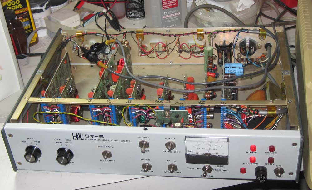
The HAL ST-6 is quite a different beast, as compared to the computers I’ve been working with over the years. There is a lot of hand wiring in it, and each module is filled with discrete components along with a few op-amps.

inside the HAL ST-6
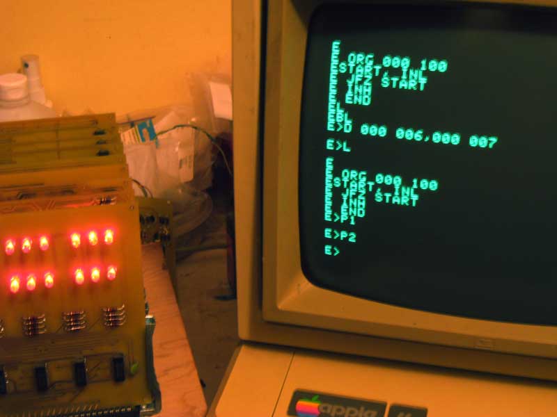
The RTTY signal comes in several forms. My mid 70’s era HAL ST-6 was designed to support demodulating a signal with frequency shift keying offset of 170, 425 or 850 Hertz. Instead of a teletype, my plans are to have a vintage computer decode the serial stream and display the incoming data. I’m starting with an Apple IIe and have written a driver for the old serial printer board that supports current loop. The driver reads 45.45 baud 5 bit BAUDET format, converts it to ASCII, and displays it on the screen. Eventually I hope to be able to port this code over to a SCELBI.
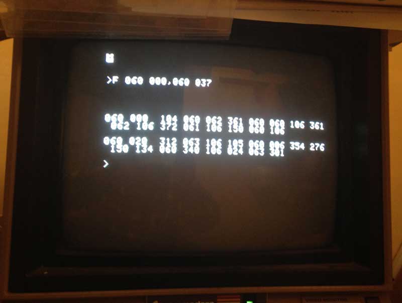
For testing purposes, I’m using an internet RTTY audio stream. This audio is routed from a computer speaker output to the HAL ST-6 audio input. This audio stream replaces the radio’s audio output of a real RTTY stream, which would normally come from the speaker output of the radio. At this point, except for a few quirks with my Apple II software, it seems to be working quite nicely. Once I get the kinks worked out of the software, I’ll hook it up to my radio, and see if I can tune in some real RTTY broadcasts.
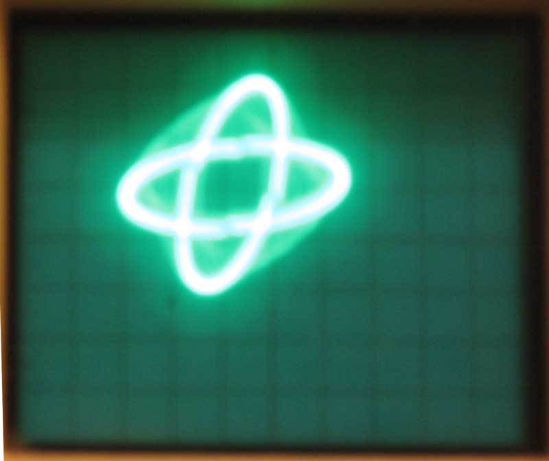
RTTY tuning in the old days was enhanced by hooking an oscilloscope in XY mode to the oscilloscope output of the ST-6. I have done the same with this test stream and think I have a pretty good pattern.
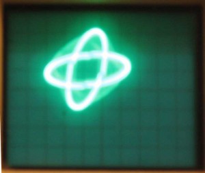
RTTY eye pattern
Getting the HAL ST-6 up and running wasn’t trouble free. At first, the output of the 170 Hertz filter/limiter wasn’t working at all. It took quite a bit of debugging before I discovered that a potentiometer case was shorted against the windings of a coil. While debugging this issue, I found and repaired a broken wire on another coil. I also tweaked the “alignment” and spent considerable time just checking out the circuit to make sure everything was working correctly. I also spent a lot of time chasing “issues” that turned out to be operator error, but I learned a lot in the process.
Once I get reception working well, and get a handle on how real operations work on HAM RTTY, I’ll start working on the transmit side of things. This HAL ST-6 has an audio FSK modulator incorporated in it. I’ll have to be cautious about how I bring it up, since AFSK operations are well known to have a lot a issues with harmonics and spurious noise.