Further SCELBI 8H Power Supply Considerations

Since I’m almost to the point of building my prototype SCELBI, I have to figure out how I’m going to power the SCELBI during initial bring up. While, later on, I intend to put together a linear supply similar to what SCELBI sold, for now I’m going to make do with more modern supplies. First thing to do is to look at requirements.

The SCELBI 8H requires two supplies, +5 volts and -9 volts. Here is what the SCELBI “ASSEMBLY AND INSTALLATION INSTRUCTIONS AND SYSTEM DOCUMENTATION” says about power requirements.

“CONNECTION OF THE POWER SUPPLY

THE SCELBI-SH MINI-COMPUTER REQUIRES A POWER SUPPLY CAPABLE OF DELIVERING +5 VOLTS AND -9 VOLTS (PLUS OR MINUS 2%.) THE CURRENT REQUIREMENTS OF THE SUPPLY DEPEND ON THE AMOUNT OF MEMORY IN THE SYSTEM (AND ANY ADDITIONAL PERIPHERAL UNITS WHICH MAY BE CONNECTED TO THE SUPPLY.) THE AMOUNT OF CURRENT THAT THE POWER SUPPLY MUST BE CAPABLE OF DELIVERING WHILE MAINTAINING ADEQUATE VOLTAGE REGULATION BE DETERMINED FROM THE FOLLOWING DATA.

THE BASIC SCELBI CARD SET CONSISTING OF ONE EACH OF: SCELBI #1100 CPU CARD, SCELBI #1101 DBB & OUTPUT CARD, SCELBI #1102 INPUT CARD, AND SCELBI #1104 FRONT PANEL CARD; REQUIRES A MAXIMUM OF 1.5 AMPS AT +5 VOLTS AND 100 MILLIAMPERES OF -9 VOLTS.

EACH “PAGE” OF MEMORY IN THE SYSTEM (256 WORDS) REQUIRES 200 MILLIAMPERES OF +5 VOLTS AND -9 VOLTS.

THE CURRENT REQUIREMENTS FOR ANY ADDITIONAL PERIPHERAL UNITS UTILIZING THE POWER SUPPLY MUST BE ADDED TO OBTAIN THE TOTAL CURRENT THAT THE POWER SUPPLY MUST PROVIDE.

FOR EXAMPLE: A BASIC SCELBI-8H EQUIPPED WITH 1024 WORDS OF MEMORY
(4 PAGES) REQUIRES: 1.5 A + (4 X .2 AMPS) = 2.3 AMPS OF +5 VOLTS AND
.1 A + (4 X .2 AMPS) = .9 AMPS OF -9 VOLTS.”

Now, as far as the -9 volt supply goes, this rating appears to be very conservative, at least on paper. There are only two ICs that use -9 volts on the SCELBI 8H, the 8008 processor, and the 1101 SRAM. Reading the spec sheet shows that the 8008 consumes a max of 60 milliamps and the 1101 SRAM a max of 19 milliamps per chip. Typical values are 30 milliamp for the 8008 and 13 milliamps for the 1101.

If the spec sheets are correct, then the base board set would typically draw 30 and max of 60 milliamps. Each page of SRAM would typically draw 13×8 = 104 and max of 19×8 = 152 milliamps. My initial bring up will involve the 4 base board set and 1 SRAM card with 4 banks populated. Max value for this setup is calculated as 152×4 = 608 + 60 or 668 milliamps. The 900 milliamps SCELBI recommends for this config, would give plenty of margin, and just to make choosing a supply easier, I’ll round up to see if I can find a minimum of a 1 amp supply for the -9 volts. Since typical values of a system with 1K might be around 104×4 + 30 = 446 milliamps, I may actually be able to power 2K of SRAM with a 1 AMP -9 volt supply.

The same calculation on the 5 volt supply is much more involved, since it literally involves counting current consumption of every component in the system, so I’ll go with SCELBI recommendations of 2.3 AMPS, but for sanities sake I’ll round up to 3 AMPs as a minimum for the 5 volt supply.

This is for initial bring up. Eventually I’ll want to test a fully populated system, with accessories. Once I have bring up done, I can measure actual consumption and increase power supply requirements based on measured values. Just in case I can start with with power supplies that will handle a full system at initial bring up, I’ll use SCELBI’s recommendations to calculate requirements for a full 4K, 8H system.

That would be 16 pages x 200 milliamps of 5v and -9v for memory, plus the base of 100 milliamps of -9 and 1.5 amps for 5 volts. Total would be 16 pages x.2 amps = 3.2 amps + .1 = 3.3 amps for -9 volts. For 5 volts, 16 pages x .2 amps = 3.2 amps and +1.5 amps = 4.7 amps. I’ll round up the 3.3 AMPs of -9 volts to 4 AMPs and 4.7 AMPS of 5 volts to 5 AMPS.

Ok, so now I know requirements for 8H power supply for bring up and and have a target for full system testing.

Minimum (bring up) for -9 volts is 1 AMP and full system is 4 AMPs
Minimum (bring up) for 5 volts is 3 AMPs and full system is 5 AMPs

What is the most practical way to provide +5 and -9 volts, at these power levels.

I actually have all the components in my Mimeo parts stash, except the -9 regulator, to build a linear supply that would meet this requirement. I actually have the -9 volt regulator, but it would have to stripped off my 1101 SRAM tester.

There are some downsides to this approach as it uses up some hard to find Mimeo parts, it would not be sufficient for a 4K 8H system, and it would take some time to put together and test.

To me, the best answer, is to use off the shelf variable “bench” power supplies. These will be useful for a number of other projects down the road and decent ones provide readouts on current consumption, which a basic homemade supply will not provide. I did a little investigation and there is an easy way to supply both positive and negative voltages to a circuit, if you have a couple of bench supplies with “floating” outputs. Here is a link to BK Precision’s description about how to do it.

http://kb.bkprecision.com/questions.php?questionid=224

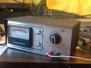
Micronta 22-123

Micronta 22-123

For initial bring up, I need 2 bench power supplies (or a single dual supply) with floating outputs for bring up. I already have an old Micronta 22-123 1 AMP 0-25 volt variable DC supply. I’ve had this supply so long, that I don’t even know when or where I got it. It’s been through the wars, having been repaired a number of times. For a long time it operated intermittently, but a year or two ago, I reflowed the solder on the power transistor pins, and it’s been solid, since. Since it will supply 1 AMP, it should work as the -9 volt supply for bring up, assuming that it has floating outputs. Even though I’ve had it a long time, I’ve always run it independently of other power supplies, so I wasn’t sure about that.

After failing to find a manual online, I checked for connectivity between the AC plug and the terminals and there was none. This was a good sign. To prove that the outputs were floating I connected the plus side to the ground on an Apple II motherboard. I connected this through a 5 ohm, 5 watt power resistor to the negative terminal of the power supply. Since the resistor was rated at 5 watts, I could run 1 AMP through the 5 ohm resistance when the power supply was set to 5 volts. This would give me a good indication that I could supply the SCELBI at -9 volts at 1 AMP with this power supply. Next, I connected a voltmeter on each side of the resistor, so I could measure current and voltage.

Before turning on the Apple II or power supply, I cranked the voltage on the power supply all the way down. Now I turned on the Apple II and started running a 2102 SRAM test, that I already had it set up to run. I made sure that it was running correctly and turned on the Micronta 22-123 power supply with crossed fingers. Nothing happened, as I hoped. I made sure the Apple II continued to run the SRAM test, before starting to turn up the voltage. Everything performed as expected, the supply providing 1 AMP of current at -5 volts with no problems, at all. The Apple continued to run the SRAM test, with no glitches. It appears that this supply will work fine as the bring up -9 volt supply. Half the bring up power supply problem is solved.

The other half of the power supply problem is deciding upon a new bench supply to support 5 volts. I’ll blog about my decision process in an upcoming post.

Beginning of Year Retro Update

Mimeo’s

Last weekend, I sold the last of the Mimeo PCBs (Glossy and Matte) that I had in stock. I will make some more matte after I’ve sold some of the first batch of the SCELBIs. I’m down to 4 ACI cards, so I’ll have to do a batch in matte to go with the next batch of Mimeos.

The new movie, “jOBS” will premiere at the Sundance Film festival this month. I’m hoping that the Mimeo PCBs that I sold to the prop house supporting the film, get some screen time and the film is good enough to get some decent reviews.

I still have plans to do a full built up system, but that project will have to wait until I have the SCELBI going. I am sorry that this has been teaser for some folks who have been waiting for it. However, I’m hoping that when I finally get to it, that folks will be impressed with the results, and say that the wait was worth it.

The new run of Datanetics PCBs have been trickling out, maybe a little faster than I expected, given the difficulty of finding components. They have mostly been combined with Mimeo PCB sales. I really wonder how many will get built up. This datanetics PCB batch has been done more of a service to the retro community, as it will be a while before this project breaks even financially.

SCELBI

Quotes from Advanced Circuits on SCELBI boards are about half of what I expected, which is awesome. Nashua Circuits came in as expected, so I guess Advanced will get this business, unless Nashua can do much better (I’ll give them a chance to improve their quotes). Since there is no solder mask, it really shouldn’t make much of a difference who makes them.

Design checks on the base 5 board set is done, and I’m about ready to declare victory on the layout tweaking/matching. The 8H backplane is just about ready, so I’ll probably get a batch of those made to go with the base 5 board 8H set, making it a 6 board set. The backplane has been challenging, as there is no schematic, only a wire list intended for wiring your own chassis. Good images of the top of backplane are non-existant. My orders for the PCBs may go in, as early as this week.

I do have one thing to check on the CPU board. There were at least two versions of the CPU board made, I am replicating a later version. There is a report of an issue with the step function reported SCELBI digest, issue II. Though describing a problem in a later version of the CPU board, this report shows a slightly different design than the one in the version of the schematics/layout that I am replicating. I just need to make sure the schematics that I’ve followed are accurate.

At this writing, estimates for the set of 6 PCBs, with an 8008D thrown in, but no other components, is in the range of 300 dollars. Final price might vary a bit, but I doubt that I could make it go any lower, without making this a one off effort, not to be repeated.

A friend of mine, is looking into doing a reproduction bezel for the front panel of the chassis. He tells me that there are some challenges, as the original was anodized, and most panel manufacturers, these days, do powder coating.

Today, I am going to see if I can generate a BOM (bill of materials) in an excell spreadsheet. Except for the 8008 and memory, I think most of the rest of the electronics components are readily available. I plan on sending the BOM to Unicorn, who have indicated, a while back, that they would do parts kits for this project, like they have for the Mimeo/Apple 1. The relay sockets used for I/O ports in the chassis, are available, but expensive – I’m going to see if I can find a way to get bulk price on those from someone.

The 8B will follow on the heals of the 8H, It uses the same front panel, CPU, DBB, and input boards as the 8H, but requires 4 new boards…

  • new backplane with an extra slot for the memory addressing board. I haven’t investigated in detail, but I hope I can leverage most of the 8H backplane design, making this pretty straightforward
  • new 4K memory module. I already have done the base chip placement for this one
  • PROM board. Cameron Cooper has a draft design, that he says he will let me leverage
  • memory address expansion card – haven’t started
  • All in all, you can see that based on the head start that I have on the 8B boards, this shouldn’t take nearly as long as the 8H has taken, to complete.

    After these are done, there is more SCELBI hardware to be done, a TTY interface, a scope interface and a cassette interface. Power supplies are another potential future project. For now you will need to find a 5 volt and -9 volt supplies. Amperage ratings depend upon the amount of memory and peripherals. According to SCELBI documentation, system with a keyboard, oscilloscope interface, and cassette interface requires the following.

  • 4K memory requires 5 volts at 6 AMPs and -9 volts at 3 AMPs
  • 1K memory requires 5 volts at 3 AMPs and -9 volts at 1 AMP
  • I’m also likely to do an automated front panel controller with a micro-controller, to make loading the memory on the 8H easier. I might be able to reuse my existing PS/2 adapter with a new program in order to accomplish this.

    Brain Board

    Brain Board stock is dwindling, but sales have been very slow, as of late. When the stock runs out, I’ll definitely hold off on making a new run, until demand builds up again.

    SUPERPROTO

    So far, interest has been a bit lighter than expected. However I’ve got wind of a couple of super cool SUPERPROTO based projects, that may just jumpstart sales when the projects are publicly announced. Feedback from folks using the card has been positive, with no unexpected problems or issues reported. I also know of one, well known, Apple II hardware designer that is leveraging parts of the design, which I have published in detail on the SUPERPROTO Wiki, for his next efforts. Even though, I get no financial reward from this leveraging, it is gratifying to know that my efforts are of use to others.

    Apple II rev 0

    A rerun of these PCBs is also in the cards, though I want to make a few tweaks, so it will also come after the SCELBI and probably the fully built Mimeo.

    That is all the retro stuff that I can think of, for now – Happy New Year

    SCELBI update – design sent off for quotes.

    Layouts for for the five boards needed to build a SCELBI 8 H are near final. I’ve done all the design checking using my software as well as cross checking with schematics and I’ve sent gerber files to an online fab house design checker. I’m also getting quotes for pricing.

    Just to give you an idea of how much work this has been, I’ve gone through the following approximate number of revisions of each board.

    CPU – 81 revisions – this was the first board I started on, so some basic SCELBI things were figured out while doing the work for this board
    DBB – 39 revisions
    INPUT – 34 revisions
    1KSRAM – 35 revisions
    Front Panel – 16 revisions – most basic board, by far

    The grand total number of layout revisions I’ve made since I started in earnest in October of 2011 is over 200.

    I’ve also been working on the backplane, but it is not quite ready. The SCELBI 8H can be built without a backplane by hand wiring, and I’m likely to build my prototype initially that way, but getting a backplane made sooner rather than later, is not out of the question.

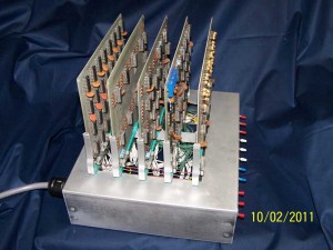
    Here is a picture of Curtis’s hardwired 8H (image provided by Curtis)

    SCELBI quick update

    Just a quick update on SCELBI progress…

    I have completed schematic layout comparisons of three of the five main 8H boards. What this means, is that I have compared the layout to the schematics and corrected any unexplainable differences between the two. This is a time consuming process, but I did find a few mistakes in my layout, so this has been worthwhile. I also found (for the second time) that there is one small mistake in the DBB board schematic. I also discovered that there were two versions of the DBB board made (I am laying out the later version) The boards I have completed this check on, are the front panel board, the CPU board and the DBB board. The CPU and DBB boards are fairly complex and took a while to do.

    The remaining boards, input and 1K memory, are less complex and shouldn’t take quite so long. After these two boards are checked, I have to do some checking of pads and hole dimensions for discrete components. I learned some time ago that getting hole sizes right is as critical as any other single part of this process. After the dimension checks are complete, I have a final CAD check left to do, before getting quotes and the boards sent off to be made.

    I also have done some work on the 8H backplane. The backplane is starting to shape up, but I’m not sure if I will have these built along with the five main cards or not, since with a SCELBI you can hardwire a backplane.

    SCOPEWRITER Revisited

    I spent a couple of evenings taking another look at the SCOPEWRITER. Followers of my blog will remember that last spring, I declared the SCOPEWRITER project a failure. At that time I put it away, knowing that eventually I would make another attempt at getting it going. Well, I have good news, at this point, I can’t call it a failure, it might even be called a qualified success.

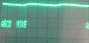
    Here is an image of the output, that I was able to create.

    Scopewriter

    I had to make two changes from where I left off, in order to get this output.

  • After entering characters, I had to disconnect the PS/2 keyboard that I had attached to it. The extra power draw of the PS/2 keyboard was too much for the power supply. As I use one of my PS/2 to ASCII adapters to get input to the SCOPEWRITER, I left the PS/2 adapter attached but unplugged the keyboard from the adapter. So I enter characters using the keyboard, then unplug it from the PS/2 to ASCII adapter. You can still see some 60HZ ripple on the output, but it’s not a showstopper.
  • I had two address lines feeding the 2513 Character generator swapped, causing characters to be displayed wrong. At some point, I’ll find a reaonable price on a TMS2501 and pull the jury rigged 2513, which has caused me so much difficulty during this project.
  • So now I have a working SCOPEWRITER. Come the think about it, this may be the only working SCOPEWRITER in the world. What else will I do with it – well at some point it will make a fun output device for the SCELBI 8H and I may just have to create a web page for it. And one other thing – my point of view is that this is really a SCOPEWRITER, not a reproduction – I used instructions and PCB layout from the original magazine article to create it, just like a hobbyist would have done back in the 1970s.