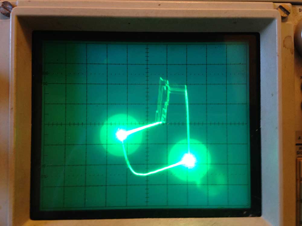
Read the article in the previous post in order to get an overview of the Oscilloscope Interface design. Here is an expanded image of a single starburst character as my implementation currently stands.
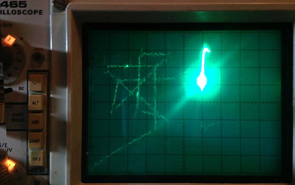
SCELBI O-scope Drawing
This is clearly not what is desired in displaying text, but you can see how the scope is attempting to draws a starburst image. In order to make more sense of what was happening here, versus what I thought the design should do, I drew a series of lines over the top of actual image.
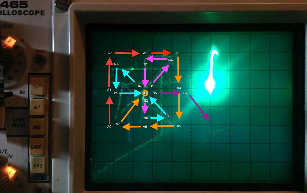
Expected Oscope Display
The software writes two bytes “A” and “B”, which controls which lines are “on” and which ones are “off”. The line starts at line “A0” and proceeds to draw through “A7”, then B0 through B7. A0 represents bit 0 of the first byte, A7, bit 7 of the first byte. B0 through B7 represent the second byte. NA represents lines that are never “on”, those lines are simply used to reposition the cursor in order to draw the next line. For purposes of debug, I had all lines turned on for this image.
Next I moved the arrows to match what is seen on the oscilloscope.
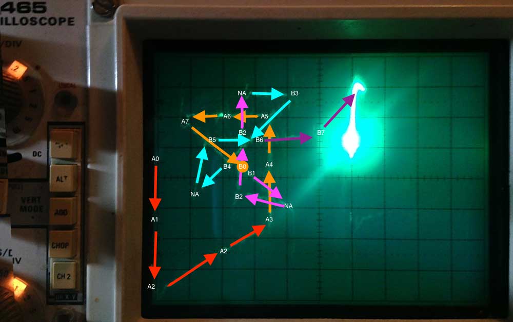
Oscope Display Trace
This technique clearly revealed two big issues, and a few smaller ones.
The first major problem is that the Y axis is inverted versus what was expected. I’ll have to investigate hardware connections to clearly understand what is going on with that. It could be as simple as incorrect hookup between the digital and analog board, or perhaps an incorrect analysis of the design. In any case, this can be handled by reversing line segment assignment in order to flip the characters.
The second issue is apparent without the process of analyzing the drawing sequence. That is the bright spot to the right of the character. That problem is actually due to the software algorythm used to draw a series of characters. An ASCII character is sent to a lookup routine that searches through a table of characters in order to find the matching bytes that must be sent to the “A” and “B” registers of the digital board. Once the lookup is complete, the 2 bytes are written to the digital board. The problem is that the scope is stuck on a single spot while the lookup is done. Even though the “Z” input should dim the scope, it isn’t turned all the way off. The solution to this problem will be to look up all the text and create a buffer of all the data to be sent to the “A” and “B” registers. That should avoid burning in one spot.
The other problems are uneven and tilted lines. I’m hoping that this can be eliminated though carefull adjustment of the variable resistors on the analog board. I’ll discuss this further in a future post as I work through those issues.
The good news with all this analysis, is that it is clear that the majority of the hardware must be working correctly in order to display this much of the starburst, as distorted as it is.