Kenwood TS-530S Alignment

Vintage radios work exclusively in the analog domain, with alignment done by adjusting numberous discrete coils, capacitors and resistive elements in the system. This is vastly different from my experience with digital computers, where, for the most part, the equipment works or it doesn’t and seldom is tuning required.

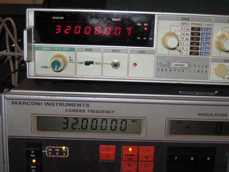
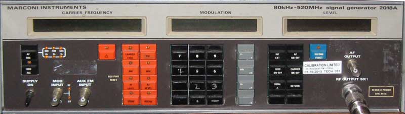
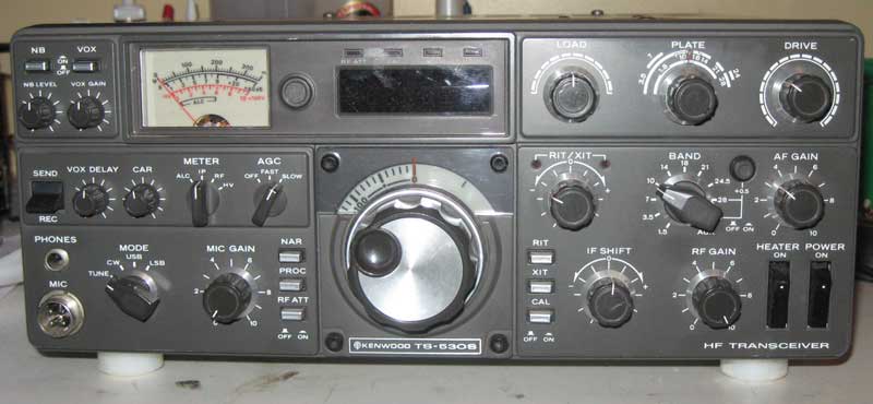
Though my Kenwood transciever has been working pretty decently, it did have one apparent issue that made me think that it needed an alignment. When switching from USB (upper side band) to LSB (lower side band), the “tone” of the audio output changed a little bit. I didn’t think that this was correct behavior and have been intending to do an “alignment”, which involves following a rather involved 25 step tune up proceedure. This is one reason that I have been acquiring test equipment, like the Marconi signal generator and Fluke counter.

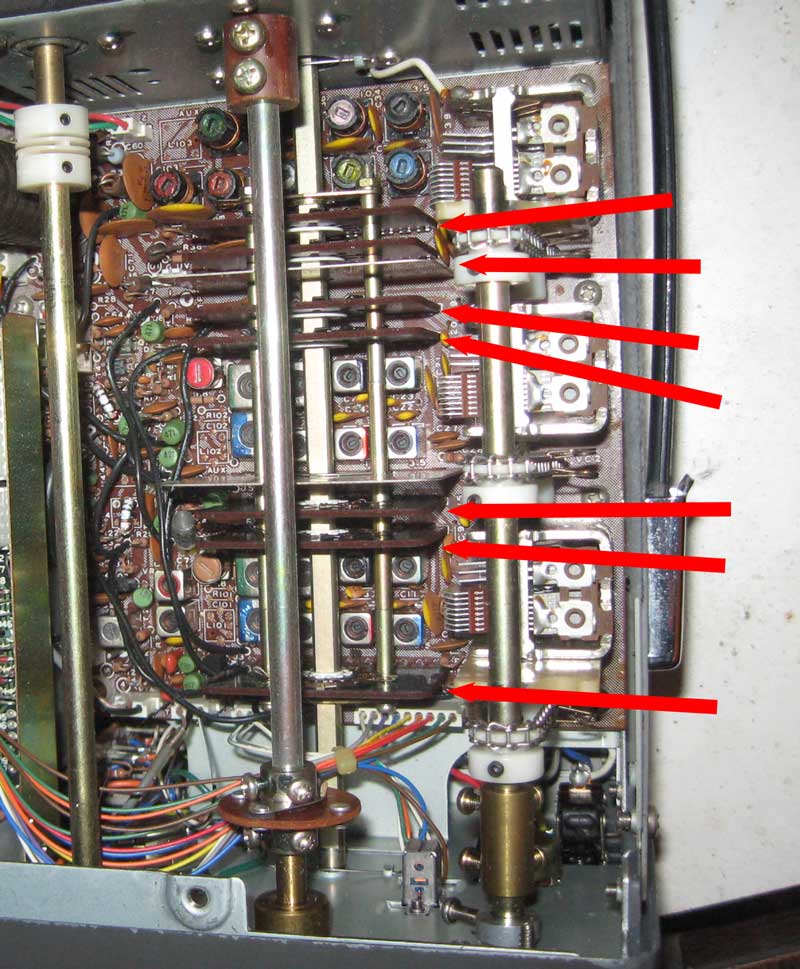
Yesterday, I spent a couple of hours in which I started the alignment process. I made it through steps 1 through 7 of the 25 step process. Oh, and I also had to skip ahead and do steps 11 and 17 when I adjusted components on the IF board instead of the PLL section ruining previous settings. As I move through the rest of the steps, I’ll have to redo those steps as the intention of the process is to do things in a certain order. This is so that later steps don’t ruin the settings of earlier steps.

I found that the job takes a lot of time, but I didn’t have any particular difficulty with any one step, other than adjusting the wrong components. This makes me think that the sections of the radio that I have adjusted don’t have any major problems.

The good news is with the completion of these steps, the difference in audio from the LSB and USB has disappeared and no other ugly phenomena has surfaced. I must be doing something right, or else I’m pretty lucky.

The reason I stopped at step 7, is that steps 8, 9 and 10 requires either going through a range of frequencies manually with a signal generator or the use of a sweep generator. I started working on building a sweep generator a month or two ago, so I’ll wait until either the sweep generator is working or is given up as a failure before continuing with the alignment. I’ll talk more about my sweep generator project in a future post.

Posted in HAM

Video Posted Showing RTTY RX with Vintage Gear

Check out my latest podcast.

feed://www.willegal.net/feed.xml

The Radio Teletype receive function seems to be working real well. The work I did in the “lab” preparing for this, resulted in almost immediate success upon hooking up my rig to a real HAM receiver.

Before I can start transmitting over the airwaves, I still have to do some work with antenna tuning, write an Apple IIe RTTY transmit driver and generally check things out in the lab. I also have some kludged cabling going on that needs to be fixed.

That said, I think that KC1CKV will soon be on the air…

73

HAL ST-6 RTTY TU Restored to Operating Order

In a previous post, I showed a picture of my HAL ST-6 RTTY Terminal Unit.

Now that I had the SCELBI 8B working, in my spare time, I have devoted a few hours to getting the ST-6 up and operating. For those of you who aren’t aware, an ST-6, demodulates a Radio Teletype (RTTY) signal and presents a current loop data stream to an external device. It was intended for connection to a Teletype, but I’m connecting it to my vintage computers.

The HAL ST-6 is quite a different beast, as compared to the computers I’ve been working with over the years. There is a lot of hand wiring in it, and each module is filled with discrete components along with a few op-amps.

inside the HAL ST-6

inside the HAL ST-6

The RTTY signal comes in several forms. My mid 70’s era HAL ST-6 was designed to support demodulating a signal with frequency shift keying offset of 170, 425 or 850 Hertz. Instead of a teletype, my plans are to have a vintage computer decode the serial stream and display the incoming data. I’m starting with an Apple IIe and have written a driver for the old serial printer board that supports current loop. The driver reads 45.45 baud 5 bit BAUDET format, converts it to ASCII, and displays it on the screen. Eventually I hope to be able to port this code over to a SCELBI.

For testing purposes, I’m using an internet RTTY audio stream. This audio is routed from a computer speaker output to the HAL ST-6 audio input. This audio stream replaces the radio’s audio output of a real RTTY stream, which would normally come from the speaker output of the radio. At this point, except for a few quirks with my Apple II software, it seems to be working quite nicely. Once I get the kinks worked out of the software, I’ll hook it up to my radio, and see if I can tune in some real RTTY broadcasts.

RTTY tuning in the old days was enhanced by hooking an oscilloscope in XY mode to the oscilloscope output of the ST-6. I have done the same with this test stream and think I have a pretty good pattern.

RTTY eye pattern

RTTY eye pattern

Getting the HAL ST-6 up and running wasn’t trouble free. At first, the output of the 170 Hertz filter/limiter wasn’t working at all. It took quite a bit of debugging before I discovered that a potentiometer case was shorted against the windings of a coil. While debugging this issue, I found and repaired a broken wire on another coil. I also tweaked the “alignment” and spent considerable time just checking out the circuit to make sure everything was working correctly. I also spent a lot of time chasing “issues” that turned out to be operator error, but I learned a lot in the process.

Once I get reception working well, and get a handle on how real operations work on HAM RTTY, I’ll start working on the transmit side of things. This HAL ST-6 has an audio FSK modulator incorporated in it. I’ll have to be cautious about how I bring it up, since AFSK operations are well known to have a lot a issues with harmonics and spurious noise.

High Value/Low Voltage Capacitor Capacity Test Circuit

High Value Capacitor Value Test Circuit

High Value Capacitor Value Test Circuit

This simple circuit can be used to test the capacity of low voltage, high value capacitors.

Use the well known RC formula: Time = Resistance * Capacitance

Connect a DC voltmeter between TP1 and TP2. Start with the 10 volt power supply switched off and the capacitor discharged. The voltmeter should read close to zero. You can short positive and negative sides of the capacitor with a resistor to discharge it.

You start the timer and switch on the power supply. Stop the timer when the voltage reaches 6.3 volts.

Since time and resistance is known you can now solve for capacitance.

Capacitance = Time/Resistance.

So if you have a 470 uF capacitor, with a 10K series resistor in the circuit, it is supposed to take .000470 * 10000 = 4.7 seconds to charge to 6.3 volts. If, in your test, it actually takes 10 seconds to reach 6.3 volts, you can calculate the actual capacitor value. In this example, 10 seconds /10000 ohms = 1000 uF.

You can increase the value of the resistor to check lower valued capacitors, but it will hard to check real small capacitors with this circuit. You can use a 555 timer circuit to check real small capacitors, but thats a subject for another blog posting.

ESR Tester

I used this 99 cent design from the web to build a basic ESR tester.

https://archive.today/301HS

After building and testing it on a solderless, plug in bread-board, I transferred it to a more permanent soldered PCB.

99 Cent ESR Tester

99 Cent ESR Tester

The idea of this design is that capacitors all have inherent resistance. This resistance can be determined by sending a fairly high frequency sine wave through the capacitor, as except for the internal resistance, a capacitor of more than a couple of uF will act like a short. The resistance can be calculated by putting the capacitor in parallel with a known resistance and using the formula for resistors in parallel.

1/R1 + 1/R2 = 1/Rtotal

Though a proper ESR tester uses a sine wave, the square wave which this circuit generates, is good enough for purposes of basically determining if a capacitor’s internal resistance is higher than expected.

I used a 10 ohm resistor in parallel with the capacitor. If the capacitors resistance is pretty high at 10 ohms, then the amplitude of the square wave, as seen on a scope at the input to both the 10 ohm resistor and the capacitor, will be halved. A low ESR of say 1 ohm will result in the amplitude of the wave decreasing by 90%. A higher resistance, such as 100 ohm will have little effect on the amplitude of the square wave. So, depending upon the specification of the capacitor, you can determine if behavior is as expected or not. Most capacitors will have a low ESR of say 1 ohm or less, which results in a dramatically reduced amplitude when attached in parallel with the 10 ohm resistor.

Here is the tester connected to a capacitor.

99 Cent ESR Tester Operating

99 Cent ESR Tester Operating

There are a few connections required to operate this tester, but they are easy to make. I connected a bench supply on the right side and adjusted to 9 volts. The capacitor is connected with alligator clips on each side of the 10 ohm resistor, making sure the polarity is correct. The oscilliscope trigger input is connected to the 555 trigger. The oscilloscope channel A is connected to the high side of the capacitor and 10 ohm resistor, which is used to read the result. This circuit could also be used to test a capacitor without removing it from the circuit.

A few notes about my build – the schematic for the 555 timer version of this tester is missing 555 pin 1 connection to ground. Though the design is adjustable, I set up my tester to run at 100 kHz. Higher frequencies would be needed for capacitors below a few uFarad in value. I didn’t have a 10 ohm resistor handy, so I connected 2 22 ohm resistors in parallel to get an effective 11 ohm resistor. This value could be adjusted higher or lower to get better readings on higher or lower value ESR capacitors. The size of the square wave you are measuring is only a few 10s of millivolts so you will need to set the vertical scale on your scope appropriately. I used 10X probes, but 1X probes would result in better resolution. My cost was actually zero, as I had all the parts to build this in scrap bins.

Fluke 1953A Counter/Timer

I just purchased a broken Fluke 1953A Counter/Timer off of eBay.

Fluke 1953A

Fluke 1953A

This one I bought as broken for $32 plus $12 shipping. The Kenwood TS-530S I mentioned in an earlier post was supposed to be completely working, so this time I figured that I would just buy a broken unit and see if I could repair it. Before purchasing, I did look at the schematics of the unit, to get a good idea of the repairability of the design. I also did some google searches to see if I could come up with common modes of failure. There are a lot of counter timers on ebay. The reason that I settled on this Fluke was that this one had a oven for frequency control and the price was right. The oven maintains the frequency source at a constant temperature, so that fluctuations in environmental conditions don’t affect the accuracy of the unit. I found one site that listed the original list price of these units at $2295, I figured my $44 purchase was quite a deal. You can buy Chinese made frequency counters for around $100, but they wouldn’t have two channels and oven based frequency source and I doubt that they would have the long term stability of a relatively ancient Fluke.

When I received the unit, I decided to open it and take a look at the internals, before powering on. Inspection of the internals didn’t reveal any obvious damage, so I decided to power it up. Turns out it powered right on, but the self test didn’t work right. The self test uses the internal frequency source to drive the display. This wasn’t working right, as the displayed value wasn’t a consistent power of 10. After a bit of poking around and a power cycle, the unit didn’t power on at all. Now I figured that I had two problems to deal with, the incorrectly operating self test and the intermittent lack of power.

I found a note on a forum about a person that replaced a power supply cap to get his Fluke 1953A eBay find working, so I suspected that I might have a bad cap. I decided I’d pull all the power supply filter caps and test them out of circuit. I tested capacitance and found that all the capacitors seemed to have better than rated value for capacitance. Next, I built a simple ESR tester and ran that test on them. The 1000uF cap did seem to have a somewhat unusual ESR behavior. After spending a few hours trying some more iterations of the same tests, I finally came to the conclusion that the other caps were almost certainly good. I decided to replace the possibly bad one and found an equivalent replacement at a nearby Radio Shack. I installed all of them and proceeded to try to power on again.

Once again no display. I started probing with an oscilloscope. What I found, is that I didn’t have any power to the capacitors at all. Probing upstream showed that no power could be found past the on/off switch. After unplugging the unit, I unscrewed the nut holding the switch to the back panel and tested the switch with an ohm meter and found it that was faulty. Luckily I had an equivalent switch in my scrap box.

Switches

Switches

The switch on the left is the original. Note the damage on the top side and the long toggle. I’m guessing that this switch took a hit on the toggle which destroyed the switch.

I put the new switch in and powered on. This time the unit came to life, and even the self test worked. I’m not sure if the self test was fixed with the power switch swap or the capacitor change, but as long as it continues to work, I’m not going to pursue it further.

Testing accuracy against my Marconi 2218A reveals that after the oven warms up, the accuracy of the two units is within 10 Hertz thoughout their range. Take a look at this side by side shot of the two units.

frequency test

frequency test

Not bad, for a unit that was last calibrated in 2002. At some point I’ll work on getting the Marconi calibrated by beating it against WWV, after which I’ll be able to calibrate the Fluke against the Marconi.

Update – I just realized the Marconi has a limit of resolution of 10 Hertz, so these two units are, in effect, in perfect calibration with each other. I guess buying quality equipment does make a difference!

Amateur Radio General License Exam

In the USA, there are currently three classes of amateur radio licenses, Technician, General and Extra. Each advancement in class gives the license holder additional broadcast privileges.

Yesterday, I passed my Amateur Radio (AKA HAM) General License exam. This gives me permission to broadcast RTTY data on a number of additional frequencies over the Technical License that I already held. Though I’m not entirely set up with the software and the hardware I need for RTTY, getting the General License is another step toward getting “on the air”.

Since passing the General test, allows you free attempt at the Extra test in the same test session, I gave it a try. Out of 50 questions, I had 29 correct, 8 short of what I needed to gain an Extra license. Since I’ve gone this far, and am apparently pretty close to knowing enough to obtain an Extra license, I figure I might as well continue studying for a couple more months and see if I can obtain the Extra license.

Posted in HAM

Marconi 2018A Signal Generator

Marconi 2018A

Marconi 2018A

I recently picked this up off of eBay for less than $200, including the cost of shipping. Though ebay is a crap shoot, this time, I think I scored. It seems to work perfectly with the frequency and power output exactly matching my Kenwood TS-530S. The seller listed it as having an intermittent keyboard problem. I haven’t see any sign of that, but did notice in the manual that if reverse power exceeds a certain level that it will lock up the keyboard until power cycled. I’m guessing that this is what happened to the previous owner. There is a calibration sticker on the front that says “CALIBRATION LMITED to Residual FM <10Hz 01-16-2013 TECH 057", so it seems that it had some sort of calibration, just last year. This unit has seem a lot of use, as the lettering on some of the keys has worn off, but I can live with that. The manual for this device lists a copyright date of 1984, so the design has been around a while. The METRICTEST.COM website says that the manufacturer list price in the US was $5,995 for the 2018. Here is a little more about the specifications of this device.

Performance Characteristics:
Minimum Frequency: 80 kHz
Maximum Frequency: 520 MHz
Frequency Resolution: 10 Hz
Time base stability: 0.1 /mo
Minimum Output Power: -127 dBm
Maximum Output Power: 13 dBm
Power Resolution: 0.1 dB
Output Accuracy: 1 dB
Output Impedance: 50
Ohm Maximum Single-Side-Band Noise: -130 dBc/Hz
Harmonics (noise): -30 dBc
Non-harmonics (noise): -60 dBc
Modulation: AM, FM, Phase

What am I going to do with this unit? Well besides confirming that my Kenwood TS-530S is in tune, I’ll also be able to test out the HAL ST-6 and use it to develop the software I need to successfully receive RTTY messages with my vintage computers.

New Toy

Kenwood TS-530S

Kenwood TS-530S

This is another new toy of mine. It is a early 80s vintage HF transceiver that will be used as critical piece of the new aspect of my Vintage Electronics Hobby that was previewed by a post showing another device. This Kenwood TS-530S was purchased as working with new tubes. Like many things on ebay, the reality of the condition wasn’t quite up to advertisement. First power up revealed an issue with intermittent operation. Investigation on the web shows that there are frequent problems with the band switch with these units. I found a couple of tutorials online and preceded to tear it apart.

Band Switch

Band Switch

Though I was a bit intimidated at first by the number of discrete components, the more I worked on pulling this device apart, the less concerned and more intrigued I became. The red arrows show the 7 boards that contain wipers and contacts that are rotated by the bandswitch. I pulled each of them out and checked for connectivity in each position. I found a couple of the wipers were not making any contact at all. I also smelled what I thought probably was tuner cleaner, so someone probably already tried to rectify the issue by cleaning contacts, but based on what I found, that approach had no chance of success. I corrected all the issues that I found and re-installed everything and now it appears the bandswitch probably is working correctly. One thing I did in addition to the normal instructions was measure each of the spacers with a dial micrometer so I was sure I could replace them correctly, should I accidentally mix them up. In case someone else has an issue on a TS-530S, the measurements of each spacer, starting from the front are .1″, .6″, .6″, .2″, .25″, .5″, .35″, .2″, .25″, .15″, .2″, .2″. I was a bit surprised that the measurements of this Japanese made device were in thousands of an inch, but maybe that is because PCB layouts are frequently done in that measurement system.

I’m not 100% sure that all is well. I haven’t done any transmitting and I decided I need to align/recalibrate the entire transceiver before declaring success and moving on. I have most of what I need to do this, but I do need to build a dummy antenna load and find a signal generator. Oh boy, an excuse for more gear. Stay tuned for new adventures in this new aspect of my vintage electronics hobby.

73s
KC1CKV

Posted in HAM