ESR Tester

I used this 99 cent design from the web to build a basic ESR tester.

https://archive.today/301HS

After building and testing it on a solderless, plug in bread-board, I transferred it to a more permanent soldered PCB.

99 Cent ESR Tester

99 Cent ESR Tester

The idea of this design is that capacitors all have inherent resistance. This resistance can be determined by sending a fairly high frequency sine wave through the capacitor, as except for the internal resistance, a capacitor of more than a couple of uF will act like a short. The resistance can be calculated by putting the capacitor in parallel with a known resistance and using the formula for resistors in parallel.

1/R1 + 1/R2 = 1/Rtotal

Though a proper ESR tester uses a sine wave, the square wave which this circuit generates, is good enough for purposes of basically determining if a capacitor’s internal resistance is higher than expected.

I used a 10 ohm resistor in parallel with the capacitor. If the capacitors resistance is pretty high at 10 ohms, then the amplitude of the square wave, as seen on a scope at the input to both the 10 ohm resistor and the capacitor, will be halved. A low ESR of say 1 ohm will result in the amplitude of the wave decreasing by 90%. A higher resistance, such as 100 ohm will have little effect on the amplitude of the square wave. So, depending upon the specification of the capacitor, you can determine if behavior is as expected or not. Most capacitors will have a low ESR of say 1 ohm or less, which results in a dramatically reduced amplitude when attached in parallel with the 10 ohm resistor.

Here is the tester connected to a capacitor.

99 Cent ESR Tester Operating

99 Cent ESR Tester Operating

There are a few connections required to operate this tester, but they are easy to make. I connected a bench supply on the right side and adjusted to 9 volts. The capacitor is connected with alligator clips on each side of the 10 ohm resistor, making sure the polarity is correct. The oscilliscope trigger input is connected to the 555 trigger. The oscilloscope channel A is connected to the high side of the capacitor and 10 ohm resistor, which is used to read the result. This circuit could also be used to test a capacitor without removing it from the circuit.

A few notes about my build – the schematic for the 555 timer version of this tester is missing 555 pin 1 connection to ground. Though the design is adjustable, I set up my tester to run at 100 kHz. Higher frequencies would be needed for capacitors below a few uFarad in value. I didn’t have a 10 ohm resistor handy, so I connected 2 22 ohm resistors in parallel to get an effective 11 ohm resistor. This value could be adjusted higher or lower to get better readings on higher or lower value ESR capacitors. The size of the square wave you are measuring is only a few 10s of millivolts so you will need to set the vertical scale on your scope appropriately. I used 10X probes, but 1X probes would result in better resolution. My cost was actually zero, as I had all the parts to build this in scrap bins.

Fluke 1953A Counter/Timer

I just purchased a broken Fluke 1953A Counter/Timer off of eBay.

Fluke 1953A

Fluke 1953A

This one I bought as broken for $32 plus $12 shipping. The Kenwood TS-530S I mentioned in an earlier post was supposed to be completely working, so this time I figured that I would just buy a broken unit and see if I could repair it. Before purchasing, I did look at the schematics of the unit, to get a good idea of the repairability of the design. I also did some google searches to see if I could come up with common modes of failure. There are a lot of counter timers on ebay. The reason that I settled on this Fluke was that this one had a oven for frequency control and the price was right. The oven maintains the frequency source at a constant temperature, so that fluctuations in environmental conditions don’t affect the accuracy of the unit. I found one site that listed the original list price of these units at $2295, I figured my $44 purchase was quite a deal. You can buy Chinese made frequency counters for around $100, but they wouldn’t have two channels and oven based frequency source and I doubt that they would have the long term stability of a relatively ancient Fluke.

When I received the unit, I decided to open it and take a look at the internals, before powering on. Inspection of the internals didn’t reveal any obvious damage, so I decided to power it up. Turns out it powered right on, but the self test didn’t work right. The self test uses the internal frequency source to drive the display. This wasn’t working right, as the displayed value wasn’t a consistent power of 10. After a bit of poking around and a power cycle, the unit didn’t power on at all. Now I figured that I had two problems to deal with, the incorrectly operating self test and the intermittent lack of power.

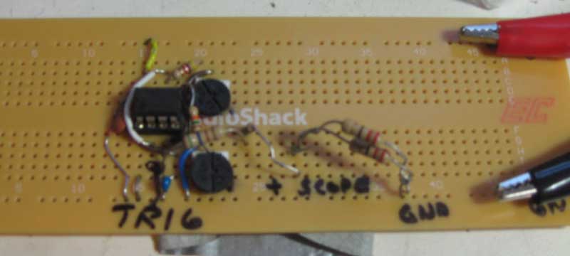
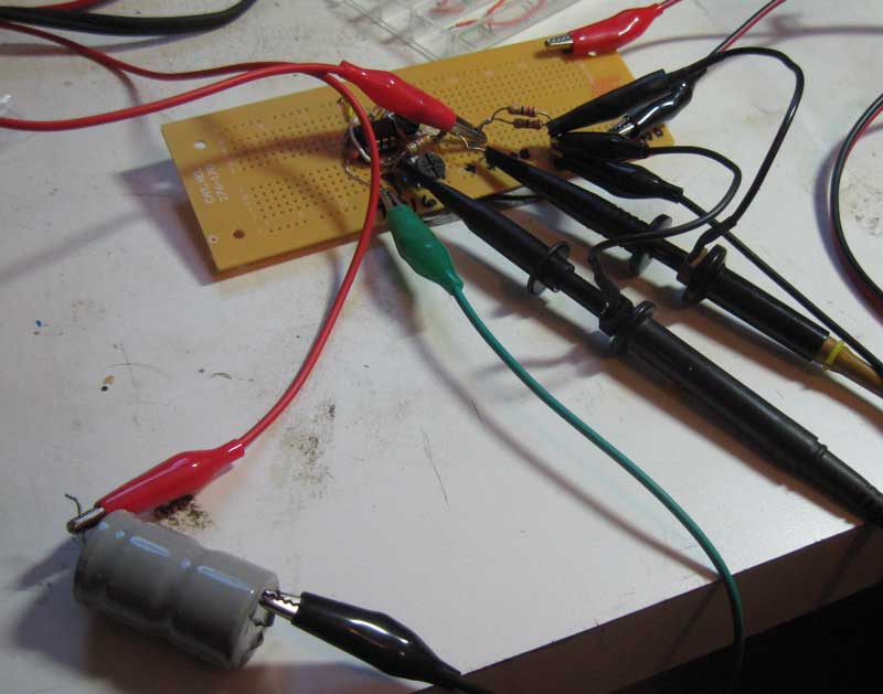
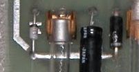
I found a note on a forum about a person that replaced a power supply cap to get his Fluke 1953A eBay find working, so I suspected that I might have a bad cap. I decided I’d pull all the power supply filter caps and test them out of circuit. I tested capacitance and found that all the capacitors seemed to have better than rated value for capacitance. Next, I built a simple ESR tester and ran that test on them. The 1000uF cap did seem to have a somewhat unusual ESR behavior. After spending a few hours trying some more iterations of the same tests, I finally came to the conclusion that the other caps were almost certainly good. I decided to replace the possibly bad one and found an equivalent replacement at a nearby Radio Shack. I installed all of them and proceeded to try to power on again.

Once again no display. I started probing with an oscilloscope. What I found, is that I didn’t have any power to the capacitors at all. Probing upstream showed that no power could be found past the on/off switch. After unplugging the unit, I unscrewed the nut holding the switch to the back panel and tested the switch with an ohm meter and found it that was faulty. Luckily I had an equivalent switch in my scrap box.
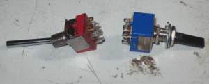
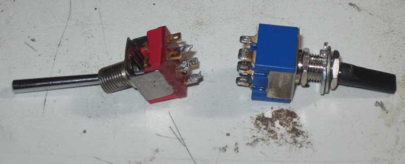
Switches

Switches

The switch on the left is the original. Note the damage on the top side and the long toggle. I’m guessing that this switch took a hit on the toggle which destroyed the switch.

I put the new switch in and powered on. This time the unit came to life, and even the self test worked. I’m not sure if the self test was fixed with the power switch swap or the capacitor change, but as long as it continues to work, I’m not going to pursue it further.

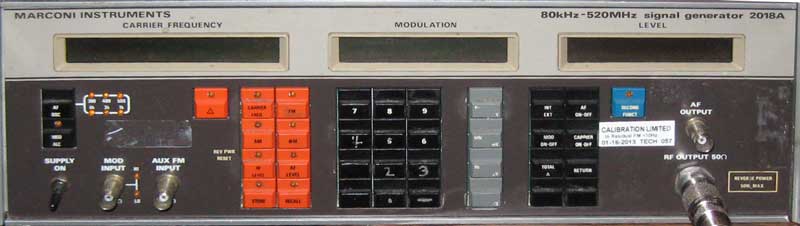
Testing accuracy against my Marconi 2218A reveals that after the oven warms up, the accuracy of the two units is within 10 Hertz thoughout their range. Take a look at this side by side shot of the two units.
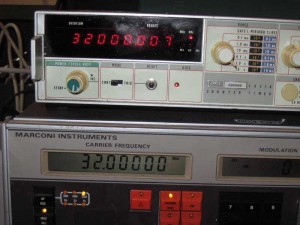
frequency test

frequency test

Not bad, for a unit that was last calibrated in 2002. At some point I’ll work on getting the Marconi calibrated by beating it against WWV, after which I’ll be able to calibrate the Fluke against the Marconi.

Update – I just realized the Marconi has a limit of resolution of 10 Hertz, so these two units are, in effect, in perfect calibration with each other. I guess buying quality equipment does make a difference!

Upcoming blog posts

Too many projects, not enough time. I have some ongoing retro tech projects that will be described in upcoming blog posts. A couple automobile repair jobs have distracted me from more enjoyable pursuits, but those are behind me now. Here is a summary of some upcoming retro blog posts.

  • SCELBI PROM PCBs have arrived, I’ll need to build a card, burn EPROMs, and fire up my reproduction SCELBI and see if I can get MEA running
  • I bought a broken FLUKE timer/counter off of eBay and will document the attempts to repair and operate it
  • As part of the timer/counter repair, I built a simple capacitor ESR (equivalent series resistance) test device. As part of this effort, I also kludged together a simple capacitance tester
  • I also bought a couple of broken external 400K floppy drives for my MAC 128K, and will describe repair efforts
  • Bob Bishop’s Apple 1 Trade In Deal – and just when did Apple II’s first ship

    Apple 1 and Apple II programmer, Bob Bishop recently passed away. Though I didn’t know Bob Bishop, I did exchange a few emails with him in June of 2013. From the few emails I exchanged with him, I got the impression that Bob was a good guy, and I feel it’s unfortunate that I never got to meet him in person.

    Back in June of 2013, while refining the Apple 1 Registry, I noticed that at one time, that Bob had an Apple 1. I sent him an email, asking if he still had his unit. Bob replied, saying that he had traded it in. This was about the time that Fred Hatfield’s Apple 1 was sold at auction. There was much in the press about Fred’s Apple 1, which included a letter from Jobs, offering a trade in deal. This was a deal which Fred had refused. Bob was a little concerned that the trade he made, wasn’t as good as what Fred and others were offered.

    Here is the story of that trade in, in Bob’s words. The article he mentions, was a New York Times article that included some mention about how aggressively Apple pursued the Apple 1 trade in program.

    When I read that article, I was a little upset (and said so on my weekly radio show) to discover that the company had “an aggressive trade-in program, offering Apple II’s and sometimes cash incentives in exchange for Apple-1’s.” When I wanted to do MY trade-in, I had to go to apple and ask THEM if they would be willing to do it. They said YES… but only if I paid THEM some additional money! But I guess that was before they had fully started their trade-in program. So it may be that I have the dubious distinction of having been the very first person to trade-in my Apple-I for an Apple-II (since the serial no. of the Apple-II that I got was 0013). 🙂

    But now that you’ve showed me the original letter from Fred, It looks like the NY Times article may have gotten their information a little mixed up. According to the letter, it appears that Fred had to pay THEM the $400 — and not the other way around (just as in my case).

    I don’t remember exactly how much I had to pay when I made my trade-in, but I think it was about the same amount ($400). And I made the trade-in around late June of 1977, but Apple didn’t ship the computer to me until July. (I remember that they said it would be delivered to my home in the next few days. So on July third, I sat around anxiously waiting for delivey. The next day was going to be the Fourth of July, and if it didn’t come today, I would have to wait two more days to get it! Well, it didn’t come… so I had a very miserable Fourth of July that year. But around 10AM on July fifth, it finally arrived! 🙂

    – Bob –

    By the way, surviving evidence indicates that though Apple 1 trade ins occurred, it wasn’t a real great deal. Several surviving Apple 1’s that came through the hands of early Apple employees, were probably trade-in’s, but there aren’t that many of them. The only person that I know of, that actually acknowledged that he traded in an Apple 1, was Bob Bishop.

    SCELBI PROM PCB Update

    diode in copper

    diode in copper (crop of image by Jack Rubin)

    Last Friday, I thought I froze the layout for the final time. I took a few looks at it, checking for correctness over the last week, finding nothing to fix or improve upon. Today, I planned on kicking off the build, after doing a final check. However, during this “last” check, I noticed that the diode symbols were missing on the front copper layer. The are not obvious, as they are obscured by the actual diodes. I’ll have to add them in, recheck the layout, regenerate the Gerbers and do some final checking (yet again). Hopefully the PCB will be ready to order by Monday. After that, it will take about four weeks, plus or minus, to be manufactured, shipped, built and tested.

    Memory Test for the 8008 Posted on my 8008 Software Page

    This was ported to the 8008 from my 6502 memory test program by Mark Arnold. I have made some modifications to his port, so any problems are solely my fault.

    It contains a couple of enhancements over the 6502 version.

  • It does not stop on error
  • It keeps a running count of errors that is displayed every pass
  • http://www.willegal.net/scelbi/apps8008.html

    By the way it’s been running for the last hour, checking out the 12K of memory installed on my reproduction 8B, without reporting any errors.

    I suppose someone who needed a good 8080 memory test could port it to the 8008 or Z80 without too much trouble.

    Woz’s take on the Apple 1’s noisy -5 volt supply

    There was a recent thread about the Apple 1’s noisy -5 volt supply on Applefritter, so I asked Woz the following:

    One thing a number of us have noticed while working with reproductions of the Apple 1, is the amount of noise that exists on the -5 volt supply. The stabiliy of the -5 volt rail appears to be affected by the edges of the -12 volt clock that is used to control the video shift registers. Usually it’s not a problem, but I’ve run across a few cases where it affected DRAM reliability. Adding additional decoupling to -5 near the shift registers and the -5 regulator seems to clean things up considerably.

    I was wondering if any of you remember noticing that noise on the -5 volt supply and if that ever was an issue back “in the day”.

    I recieved the following reply from Woz:

    I am sure that what you describe is valid, although I personally wasn’t aware of it.

    I did the prototype of the Apple I and debugged the PC board version but didn’t look into such aspects. I’m sure you are quite correct. We knew that this was a low volume product since we were demonstrating the Apple II before shipping the first Apple I. Hence, we did not have many to become aware of issues like this. Part of the problem was that my time was being spent on the Apple II completion.

    The ‘productizing’ of the Apple I came under Steve Jobs. I always optimized my prototypes for short distance wiring, but the PC board introduced longer power traces. Please forgive me. I never looked closely at this aspect. I certainly over-minimized in bypassing decoupling capacitors throughout the chips and RAM. I did worse too that was probably copied over to the PC board, like not having pullup resistors on unused TTL inputs. Still, had we at Apple been aware of such an issue while selling maybe 150 Apple I’s, we could and would easily and quickly have rectified it. But we didn’t test fully a product that was a temporary place-holder before the big product. We did try to buy back every Apple I in exchange for Apple II’s.

    We had more luck than anyone deserves with things working out just enough to suffice and do what we did.

    I will tell you that I and others did observe the power lines and did not notice noise or spiking. And, as I said, it was never a problem that was called to our attention, or at least to my attention. We could have put out an errata sheet for owners to fix the problem themselves, since this was very much a maker product (local stores could modify things to use 16K RAM’s, for example, and they did.

    I am totally interested in hearing such things even after all these decades. I awoke one night in Quito, Ecuador, this year and came up with a way to save a chip or two from the Apple II, and a trivial way to have the 2 grays of the Apple II be different (light gray and dark gray) but it’s 38 years too late. It did give me a good smile, since I know how hard it is to improve on that design.

    best,
    Woz

    Marconi 2018A Signal Generator

    Marconi 2018A

    Marconi 2018A

    I recently picked this up off of eBay for less than $200, including the cost of shipping. Though ebay is a crap shoot, this time, I think I scored. It seems to work perfectly with the frequency and power output exactly matching my Kenwood TS-530S. The seller listed it as having an intermittent keyboard problem. I haven’t see any sign of that, but did notice in the manual that if reverse power exceeds a certain level that it will lock up the keyboard until power cycled. I’m guessing that this is what happened to the previous owner. There is a calibration sticker on the front that says “CALIBRATION LMITED to Residual FM <10Hz 01-16-2013 TECH 057", so it seems that it had some sort of calibration, just last year. This unit has seem a lot of use, as the lettering on some of the keys has worn off, but I can live with that. The manual for this device lists a copyright date of 1984, so the design has been around a while. The METRICTEST.COM website says that the manufacturer list price in the US was $5,995 for the 2018. Here is a little more about the specifications of this device.

    Performance Characteristics:
    Minimum Frequency: 80 kHz
    Maximum Frequency: 520 MHz
    Frequency Resolution: 10 Hz
    Time base stability: 0.1 /mo
    Minimum Output Power: -127 dBm
    Maximum Output Power: 13 dBm
    Power Resolution: 0.1 dB
    Output Accuracy: 1 dB
    Output Impedance: 50
    Ohm Maximum Single-Side-Band Noise: -130 dBc/Hz
    Harmonics (noise): -30 dBc
    Non-harmonics (noise): -60 dBc
    Modulation: AM, FM, Phase

    What am I going to do with this unit? Well besides confirming that my Kenwood TS-530S is in tune, I’ll also be able to test out the HAL ST-6 and use it to develop the software I need to successfully receive RTTY messages with my vintage computers.

    What is SCELBI’s MEA

    Like so many other things in the SCELBI world, it’s best to let the creators describe it for you.

    THE SCELBI MONITOR/EDITOR/ASSEMBLER PROGRAM, ABBREVIATED IN THIS MANUAL AS “MEA” IS A POWERFUL SOFTWARE PACKAGE THAT COMBINES THE FUNCTIONS OF A MONITOR, EDITOR, AND ASSEMBLER IN A RESIDENT, CONVERSATIONAL TYPE ARRANGEMENT. THE PACKAGE IS STANDARDLY SUPPLIED ON A PROGRAMMABLE READ ONLY MEMORY ELEMENTS THAT RESIDE ON PAGES 60 THROUGH 77 (OCATL) FOR USE IN A SELBI-8B MINICOMPUTER. I/O ROUTINES FOR THE PACKAGE ARE SUPPLIED ON TWO SEPARATE “PROMS.” THE STANDARD SCELBI AUDIO TAPE DRIVING PROGRAM RESIDES ON PAGE 77. I/O ROUTINES FOR THE SPECIFIC I/O HARDWARE TO BE USED WITH THE SYSTEM IS PROVIDED ON A PROM ON PAGE 76. TWO STANDARD I/O VERSIONS ARE AVAILABLE. ONE FOR SYSTEMS EQUIPPED WITH THE SCELBI OSCILLOSCOPE ALPHANUMERIC DISPLAY INTERFACE AND SCELBI ASCII KEYBOARD INTERFACE, THE OTHER FOR SYSTEMS USING A MODEL 33 TELETYPE INTERFACED WITH THE SCELBI BIT-SERIAL TTY INTERFACE. OTHER TYPES OF I/O DEVICES CAN BE ACCOMMODATED BY SPECIAL ARRANGEMENT AND SUBSTITUTION OF APPROPRIATE I/O ROUTINES PROGRAMMED ONTO A PROM ON PAGE 76.

    Here is the cover of the manual, which can be found at scelbi.com.

    SEA cover page

    SEA cover page

    This development environment, which was available in 1975, was quite an achievement for the time. The environment was “robust” enough that Mark Arnold used it to develop SCELBAL. Few other “personal” computer systems available in 1975 had such capabilities built in. For instance, Microsoft BASIC for the 8080/Altair was developed in emulation on a PDP-10.

    Also at scelbi.com is a intel hex file of the contents of the PROM card. This version of the contents was painstakingly reconstructed by Mark Arnold from an object listing that was sent from Nat Wadsworth to Mark when Mark started experiencing problems with the EPROMs on his system back in the old days. It’s very fortunate that Mark saved this listing.

    Start of MEA Listing

    Start of MEA Listing

    The listing was just a raw dump and where it was folded the data was illegible. Mark and Cameron Cooper managed to get MEA up and running in emulation and used the emulator to help reconstruct the missing data, so they believe the hex file at scelbi.com is correct.

    MEA listing with missing line

    MEA listing with missing line

    The version they have, is set up for the TTY interface. So far, we haven’t been able to find a surviving version of the oscilloscope drivers that would replace the TTY drivers on page 76. I think it’s rather unlikely at this point that we will be able to find the oscilloscope version, so that version will most likely have to be rewritten from scratch.

    We have the TTY version of the MEA program and I have already done the TTY interface card, so we are getting close to having reconstructed a complete SCELBI 8B running MEA. After completing the PROM card, my next efforts will be to do the cassette interface, which will allow running the MEA system as it was intended on real hardware.

    In order to get MEA working in my OS/X emulator, I’ll need to enhance the terminal support to act more like a real TTY as CR and LF are separate functions and I’ll also need to figure out how to support backspace. I also intend to add cassette interface emulation support to my emulator to allow complete support of MEA in emulation.

    Reproduction SCELBI 8B now running SCELBAL

    This has been a very long time coming and I’m super excited to see it finally running.

    Here is a very poor quality video of it in action.

    Note that the versions of SCELBAL found on the net require 12K because they include all the available features and options. In order to run in a 8K system, the array feature is going to have to stripped out.