SCELBI Card Guides

Without card guides, the cards in my reproduction SCELBI are not as stable as they should be. They will rock back and forth a bit, even if just gently touched.

I just received a set of card guides for my reproduction SCELBI 8H. I installed the first pair on the front panel slot and they fit fine and hold the card in a very stable fashion.

BR27D card guide on reproduction SCELBI

BR27D card guide on reproduction SCELBI

The only cardguides that I could find that are still in production, are model BR27D from vector electronics.
http://www.digikey.com/product-detail/en/BR27D/V2027-ND/1886457

They are expensive, but at least they come in pairs. The screws for these guides appear to be size #4, not #6, like I had expected were used on the original SCELBI computers.

SCELBI flashing lights demo running

This demo can be found in the user manual. Took a while to toggle it in, as the front panel controls are pretty quirky. Once I got the program loaded in correctly, the system seems to run fine.

These days, this might not seem like too big of a deal, but in 1974, a SCELBI owner was likely to have the only “personal” computer in town. Running any kind of program in your own house would be a huge deal. Personally, I had to show it off to my family, so it still is a big deal to me in 2013!

I started work on putting together a cheat sheet, as the SCELBI user manual is kind of wordy, yet still is missing some important concepts, that I had to learn about, the hard way

I still need to check out memory addressing for the entire 4k memory range and I/O. This might take a couple of weeks. After that I’ll open up board sets for general sales.

SCELBI Input Card

Here is the SCELBI input card – ready to go. The SCELBI instructions were fine. The 65 10K ohm resistors take a while to solder in, but otherwise it is a very straight forward process. It draws around 200 milliamps in static, standalone condition.

SCELBI Input Card

SCELBI Input Card

Next up is 1 bank of 8 SRAM sockets on an SRAM card. Soon after that, I’ll be manipulating toggle switches!

PS/2 Adapter Repurposing

The daunting task of toggling in a program of any significant length into a SCELBI has made me consider ways of automating the process, at least for demonstration purposes. What I’m looking at, is altering the program on one of my PS/2 to ASCII keyboard adapters and connecting it to the SCELBI’s front panel connections. Here are the reasons why I think this will work out really well.

  • The front panel is controlled through TTL I/O lines pulled up to +5 volts with 1k resistors. This is something that the AVR should be able interface directly to.
  • There are more than enough I/Os available on the PS/2 card, especially if I repurpose the three configuration jumpers. There are 8 bits for data and three pushbuttons for control. In addition I should be able to tap into a couple of the CPU status lines in order synchronize with the CPU states.
  • I already have both keyboard and RS232 drivers written for this board.
  • The keyboard can be used for control and the RS232 port to get data from a host computer.
  • An alternate approach is to use RS232 for both data and control.
  • I have plenty of these boards available. I’ve used less then half of the lifetime supply that I had made when the Mimeo first came out.
  • The interesting thing about this little board, is that I can also use it for other interface applications on the SCELBI, at least until I have time to reproduce authentic 70s era interfaces that were available. Examples include:

  • RS232 interface
  • With a bit of extra hardware – cassette tape interface
  • SCELBI: to Socket or Not?

    Since the SCELBI was sold as assembled, kits or bare boards, what you do about sockets is largely up to you. However based on observations of original SCELBI mini-computers, here are some suggestions to make your SCELBI more authentic.

    Suggestions for the Front Panel, CPU, DBB and Input Boards:
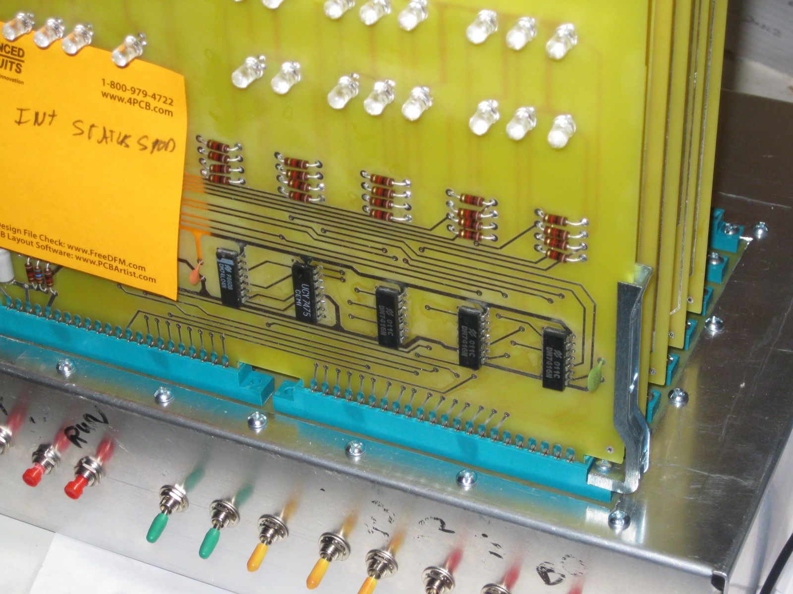
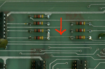
    Many of the boards that I’ve seen, use the Molex strip connectors mentioned in an earlier post for all ICs on the board. SCELBI instructions only mention using these for the 8008 and soldering the rest of the chips directly to the PCB. I have seen one original system set up this way. Since the 8008 is the only rather expensive chip used on these boards, I have chosen to follow instructions and solder all parts to the PCB, except the 8008. If I need to pull a 74xx part, I’ll cut the legs off and remove the legs individually. A friend of mine managed to obtain a roll of the MOLEX pins and I installed those for the 8008. They are rather fidgety to install, and I suspect reliability might be an issue. Even if you can find enough stock to do an entire system, I wouldn’t recommend doing a whole system with those MOLEX pins. I have also seen one 8B that used regular 70s style closed frame solder tail sockets. You should be able to find a bunch of older closed frame sockets at surplus dealers, if you want to socket your boards. I haven’t seen any SCELBIs with machine pin sockets.

    Suggestions for the Memory Cards
    Though the instructions don’t call for sockets, all the memory cards I have seen, use either MOLEX strip sockets or old style closed frame sockets. Apparently memory was expensive enough and perhaps failed often enough in those days that soldering in memory was not considered wise.

    Example Closed Frame Socket Used on SCELBI Memory Board.
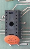
    Closed Frame Socket

    Closed Frame Socket


    I believe this one is made by SCANBE. SCANBE’s were also used in arcade machines and have a terrible reliability according to arcade system restorers. I’ve seen one page that suggests replacing all SCANBE sockets before proceeding further.

    More on Molex Strip Sockets
    Here is a page from an old (1973) MOLEX M-100 catalog
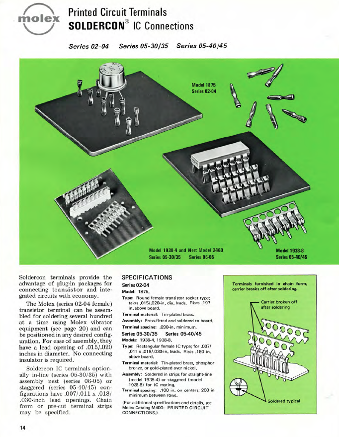
    MOLEX strip sockets

    MOLEX strip sockets

    SCELBI Front Panel and Power Wiring

    Following instructions in the manual, I wired the front panel switches. I also added a temporary jack for power, until I get something more authentic.

    Front panel and power wiring inside chassis

    Front panel and power wiring inside chassis

    With this setup, once I complete the memory and input boards, I should be able to toggle in a tiny program. Actually I may be able to toggle some instructions directly into the CPU, even without the memory card.

    The push button switches should be normally off, with one terminal connected to ground and the other to the control signal. Pull up resistors on the CPU board keep the signal high, until grounded. The toggle switches are connected in a similar fashion. Connect the center terminal to either ground or the data bus input signal and the other to the terminal such that when the switch is in the “up” position, pull up resistors on the input board keep the signal high. When the switch is in the “down” position, the signal should be connected to ground.

    DBB Nears Completion

    DBB board

    DBB board

    Here it is resting on top of an iPad (which is on top of a powerbook).

    Only thing left to do is to install the +5 volt bus workaround jumper between resistors R37 and R38 and add the 6.3 volt zerner. For some reason the +5 volt jumper wire isn’t mentioned in the SCELBI instructions. I got a bad batch of Zerners, so I’ll have to install that later on. It draws about a 1/2 amp when applying +5 volts to this board without the rest of the system connected.

    Except for the omission of the jumper, the standard SCELBI instructions seem accurate for the DBB board.

    In case you didn’t remember from my previous post, here is where the +5V jumper goes.

    +5 volt wire on DBB board

    +5 volt wire on DBB board

    6800 running on a Mimeo 1

    For a while now, we have speculated about how well a 6800 would really work in an Apple 1. Well, a 6800 is running now on a Mimeo. See Lionel’s utube video for proof.

    Eric Smith had previously created a 6800 Apple 1 monitor that he ran in emulation. Lionel took that monitor and went to work to make it run on real hardware. Lionel had to make two changes to make it work.

  • the 6800 7404 had to be changed to a slower 74L04 in order to make clock timing work
  • pin 39, which is not connected in a 6501, had to be pulled down to ground with a 10K resistor
  • Kudos to Lionel for making what I think is an Apple/Mimeo 1 first…

    SCELBI Chassis Prototyping

    Prototype Chassis with backplane installed – top view

    SCELBI chassis-top view

    SCELBI chassis-top view

    This is the result of some hacking of a backplane into a BUD AC413 chassis. The AC413 is the same width (12″) and depth (10″) as an original SCELBI chassis. However the BUD AC413 is 3 inches tall, while the original SCELBI chassis 3.5″ tall. During this prototyping/hacking effort, I found out a few important things.

  • Cutting aluminum is not hard, but it’s best to drill holes with a jig or at minimum use a punch to mark the center of the holes in the aluminum. I eventually used one of the scrap backplanes from the first delivery to create a jig for drilling holes.
  • On a “real” SCELBI chassis, the cutout for the edge connectors fits very tightly around the perimeter of the edge connectors. Making the cutout any larger than necessary, makes it very difficult to locate the support screws on the sides of the backplane. The edge connectors extend 8 7/8″ left to right and 5 5/8″ front to back. The backplane is 9.5″ wide and if the hole is made 9″ wide, that leaves only 1/4″ overlap per side to drill a 9/64″ hole for the #6 mounting screw. If possible, it would be best to cut the hole for an exact 8 7/8″ side to side fit. Though it doesn’t look like it, my prototype left too much space between the edge connectors and the chassis, making fitting the side mount screws a challenge.
  • The cutout starts 1/2″ from the front of the chassis and is centered between the edges.
  • SCELBI Chassis Bottom View

    SCELBI Chassis Bottom View

    A view from the bottom.

  • Screws holding the edge connectors/card guides have both a washer and star washer, but no lock tight on the original SCELBIs. I don’t have card guides and have used 1/2″ #6 machine screws.
  • Screws holding the backplane to the chassis have neither a washer or a star washer, but a held in place with red Locktight on original SCELBIs. I haven’t used Locktight, because I want to find shorter screws and I have more work to do on the chassis with the toggle switches and I/O connectors. The 3/8″ screws are a bit too long on my reproduction. A 1/4″ screw might be a better match to the original.
  • The screws at the front of the backplane do no go through holes in the backplane, but the edge of the nuts hold the backplane in place.
  • When soldering the edge connectors, only the pins with connections and pads are soldered.

    One more thing – I positioned one of the holes for the edge connector mounting screws 1/16″ too far back. This hole will need to be drilled out to properly fit a #6 screw. However the error is so small that the enlarged hole cannot be seen under the nut of the screw or the ear of the connector.

    An insulated stiffener running down the center of the board between the connectors would have been a good addition to this design.