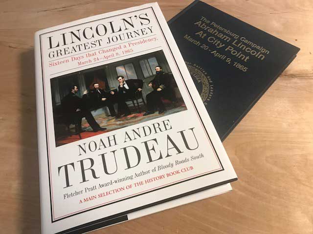
two Lincoln at City Point books
The book, “Abraham Lincoln At City Point” was written by national park historian, Donald C. Pfalz and published in 1989. My new book, “Lincoln’s Greatest Journey” was written by Noah Andre Trudeau and published in 2016.
Both books contain a remarkably similar account of Lincoln’s stay at City Point in late March and early April of 1865. I would say that Pfalz’s book is a bit more scholarly in nature. Trudeau’s book is written more for general consumption and contains more background information about what was happening with the war in general and at the Petersburg front in particular.
Despite the duplicate subject matter, for someone modeling City Point during this period in time, I can’t imagine not picking up both volumes. There aren’t really that many books that use so much ink describing what was going at at City Point, at the time.
Now, for the correction. A while back, I made this post describing a theory I had about about Lincoln’s travel to the front on March 25th.
Though I still think that Mr Pfanz was wrong in his assessment that the train took them to Patrick’s station, I was missing some information, and didn’t read the train reports closely enough.
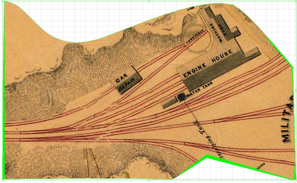
My assessment was also wrong. I should have investigated further, but it turns out that Meade’s HQ was near the Aikin’s house, which was near Parke’s station. Here is crop of Michler’s map of the Petersburg fortifications, showing the area from Meade’s HQ to Fort Wadsworth, the area that Lincoln’s party visited. I have labelled the area of Parke’s and Warren’s station, which are not noted on Michler’s original map.
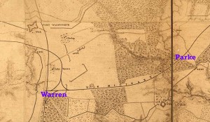
Lincoln’s Visit to the Front
It’s interesting that the train report that Bernard Kempkinski found in the National Archives doesn’t list a Parke Station at all. I suppose it was more of whistle stop, rather than a regular station. I now believe that Lincoln’s party probably left the train at Parke Station and went directly to Meade’s HQ, which would have have been proper protocol for a commander visiting his subordinates army. However, if Parke Station didn’t have the facilities to unload the horses that were brought along, the most logical first stop would have been Warren Station.
Meade’s HQ area is where Lincoln’s party saw the prisoners from the fight for Fort Stedman. I finally realized why there would be prisoners so far from where the fighting took place, which was part of my confusion in the past. Meade’s army would have had provisions and procedures for handling prisoners. During the Civil War, the army’s provost guard HQ was usually near army HQ. Most likely, all prisoners the army captured, were sent to a holding area somewhere near the provost guard HQ for processing. This is why the prisoners from the fight at Stedman were marched to near the Aiken house.
I don’t believe that Lincoln actually saw the battlefield around Stedman, itself. Since they were so far from the big fight at Stedman, I’m not really sure how many dead and wounded that Lincoln saw that day. However because of all the fighting going on across the front that day, it’s very likely that some wounded and perhaps a few men that had expired from their wounds were in the area that Lincoln visited.
From Meade’s HQ, it would have been a fairly short ride by horseback to review part of the fifth corps and then on to Fort Wadsworth. There, the party could have obtained distant views of fighting going on in the area. From Fort Wadsworth, the group could easily have proceeded down the line to Patrick’s station, before returning to City Point on the train.
I think that Trudeau’s book describes this trip to the front, pretty well, though I’m kind of skeptical about how many dead and wounded men were seen by the group.